Welcome to a new Voltlog, today we’re taking a look at a device which is not typical to be found in a hobbyist lab but one that certainly has its place with the more advanced user that has some automated test setup needs. This is the MagicDAQ and it was sent in for free for the purpose of this review, I believe it was shipped from New Zealand so I think it might be made in New Zealand.
Here is the spec list for this unit, we have:
8 analog inputs (14 bits, 48Ks/s +/- 10V), typical voltage resolution is 10mV. These can be connected single ended or differential between channels.
8 Digital inputs or outputs (0-5V)
2 Analog outputs capable of Voltage, Sine or PWM output (0-5V), 12 bit DAC resolution with up to 31KHz of output frequency.
1 Counter up to 5MHz with edge detection / PWM up to 65KHz (0-3V3) I’m guessing this can be both input and output?
One 5V output limited to 250mA, powered from VBUS rail.
It’s USB powered and comes with a DIN rail mount.
And another important feature is the way you control the hardware which is through a Python API and everyone loves python these days, however there is one important limitation here, it is only supported under Windows because of hardware driver constraints which prevent it from working under Linux and Mac.
Inside the box I got the unit, the DIN rail adapter and a USB cable, this is good practice, to include the USB cable because users might have a low quality USB cable laying around and they might decide to use that low quality USB cable with your product which might cause all sorts of trouble and head scratching as to why your product isn’t working as expected, By including a good quality cable in the box, you limit the number of things that might go wrong for the user.
Same as most people these days I do have a couple of LED tapes in my apartment to provide some ambient or work area illumination. The ones I have are warm white 12V tapes and they’re typically controlled via some sort of touch dimmer which again is a pretty typical low cost commercially available solution.
But given how the rest of my lights are fully dimmable and integrated into HomeAssistant for remote control I started thinking how I could do that for the LED tapes as well. And I think you know where this is going, yup, I’ve designed my own LED driver board, this is it, based on an ESP32 and WLED compatible but more on that in a second.
First let me mention the list of requirements that I had, before I started designing this.
My number #1 requirement was to get rid of the typical LED tape frame style power supply units which are generally big and bulky, pretty noisy in terms of electro-magnetic radiation. I have plans for installing some small lengths of LED tape and there is no point in having like a 20W power supply if I’m only going to need something like 10W at most. So I figured why not design this LED driver board to take in USB Type-C power supply input, with power delivery support. This way I could power it from one of these usb-c wall adapters. Simple, clean and reliable if used with a high quality adapter. In addition to that, I would argue that it’s safer too when used with a high quality adapter because you no longer have to deal with mains wiring.
Number #2 requirement was to have an ESP32 in there so that I could integrate this into my smart home management system. Having an ESP32 will give me plenty of processing power to run either Tasmota or ESPHome or even better WLED which specializes on LED driving capability.
Number #3 requirement was the ability to drive both digital LED tape like SK6812 or WS2812 type and analog type LED tape which you have to PWM on individual channels. I wanted up to 4 analog channels so that I could drive an RGBW tape and at least 2 digital channels but I ended up wiring 4 digital channels because I had more available pins.
Number #4 requirement was to have the whole system small so that it could be put in a small enclosure, maybe even enclosed into a wall distribution box.
Now considering these requirements one by one, I’ve successfully implemented 1 to 3, not so much on #4, because the whole system is not as small as I would have liked it to be. When fitted inside the enclosure it measures roughly 90*70*30mm and ideally I would have like it to be half of this size, something like 90*30*30mm would have been great but I just couldn’t fit everything in that size unless I was going to do a double sided assembly which I tend to avoid because it significantly raises prototyping and manufacturing costs.
So let me start with presenting some of the technical specs that I have on this driver board:
USB Type-C power input with power delivery, based on this dip switch selection, it will negotiate for 5V or 12V. For safety purposes I have also added a manual jumper that needs to be manually selected to route the resulting voltage rail to the 5V side or to the 12V side because I figured there might be edge cases where the user has a 5V led tape connected and then accidentally requests 12V with the dip switch which would result in 12V being applied to the tape.
We have a secondary power input via screw terminal for those that do not want to use USB Type-C.
We have 4 mosfets with PWM for driving RGBW 12V LED tapes.
We have 4 digital LED channels, these are properly connected via a high-speed buffer line driver that also level shifts the signals to 5V.
We have an I2S microphone which WLED supports by default for sound reactive lighting.
We have an integrated IR receiver which once again WLED support by default for remote control.
We have a touch input GPIO where you could connect some improvised touch sensing point if you would like to implement touch control.
With some of the remaining available GPIO I’ve created this I2C standard 0.1 inch header so that you may for example connect additional stuff, like a temperature/humidity sensor.
Welcome to a new InTheMail, the most popular segment hosted here on the channel. It’s been quite a while since the last InTheMail so a lot of interesting stuff has been gathering in my special bin.
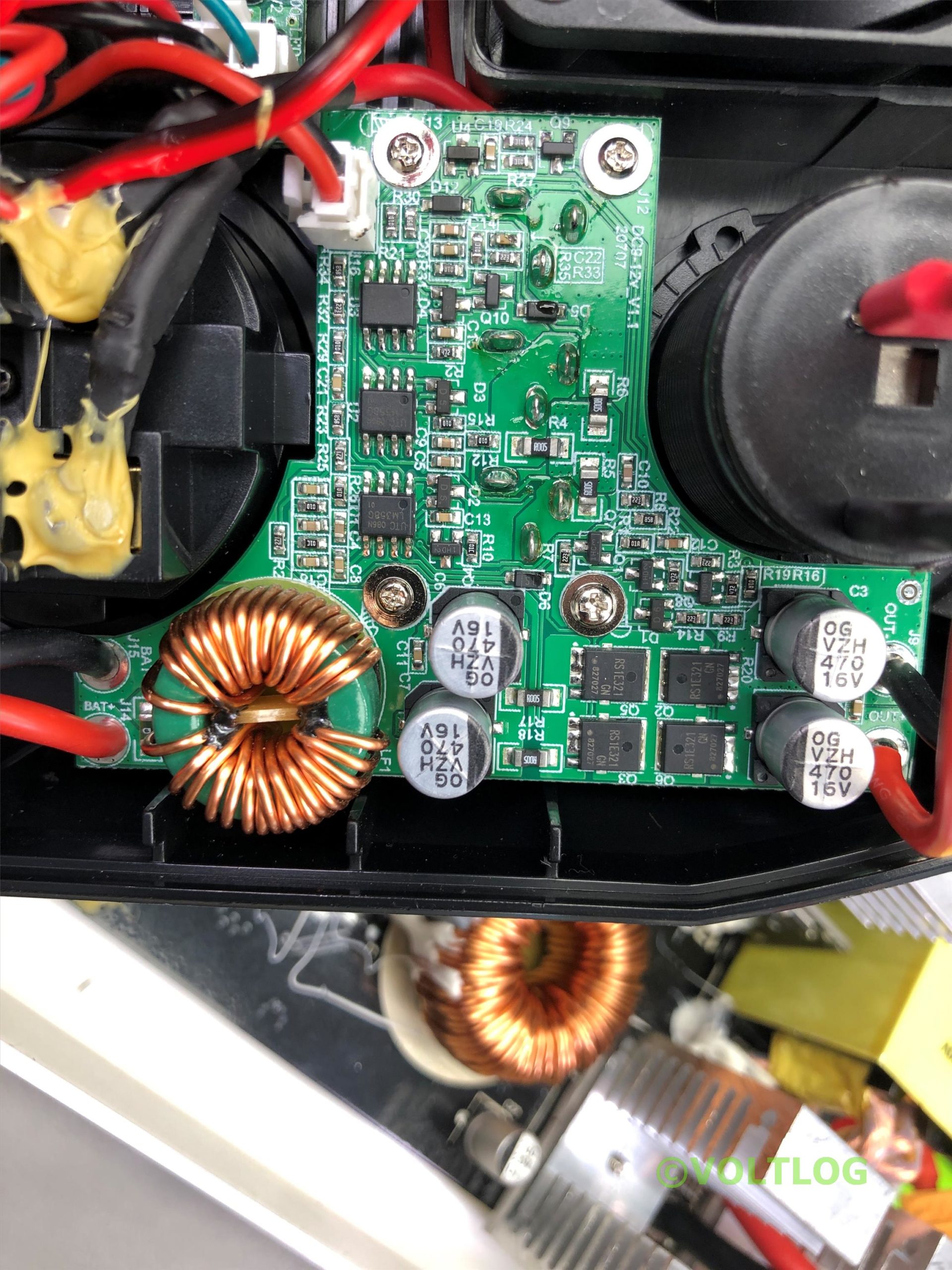
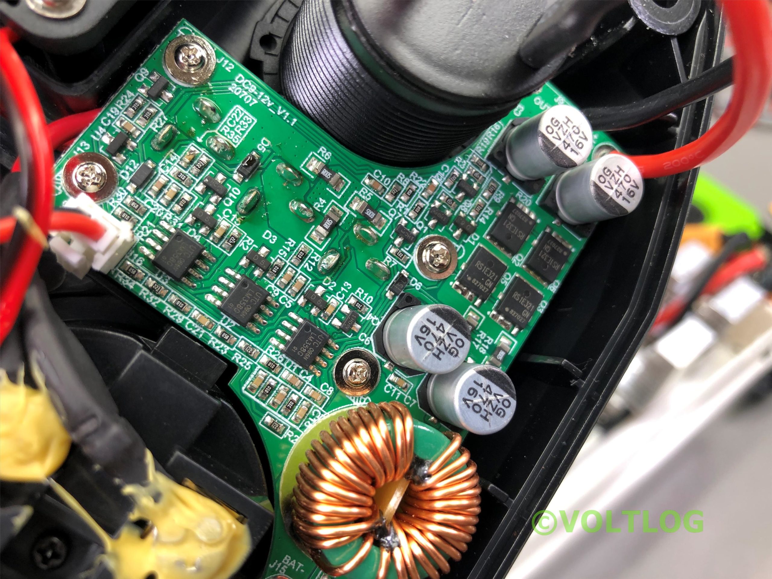
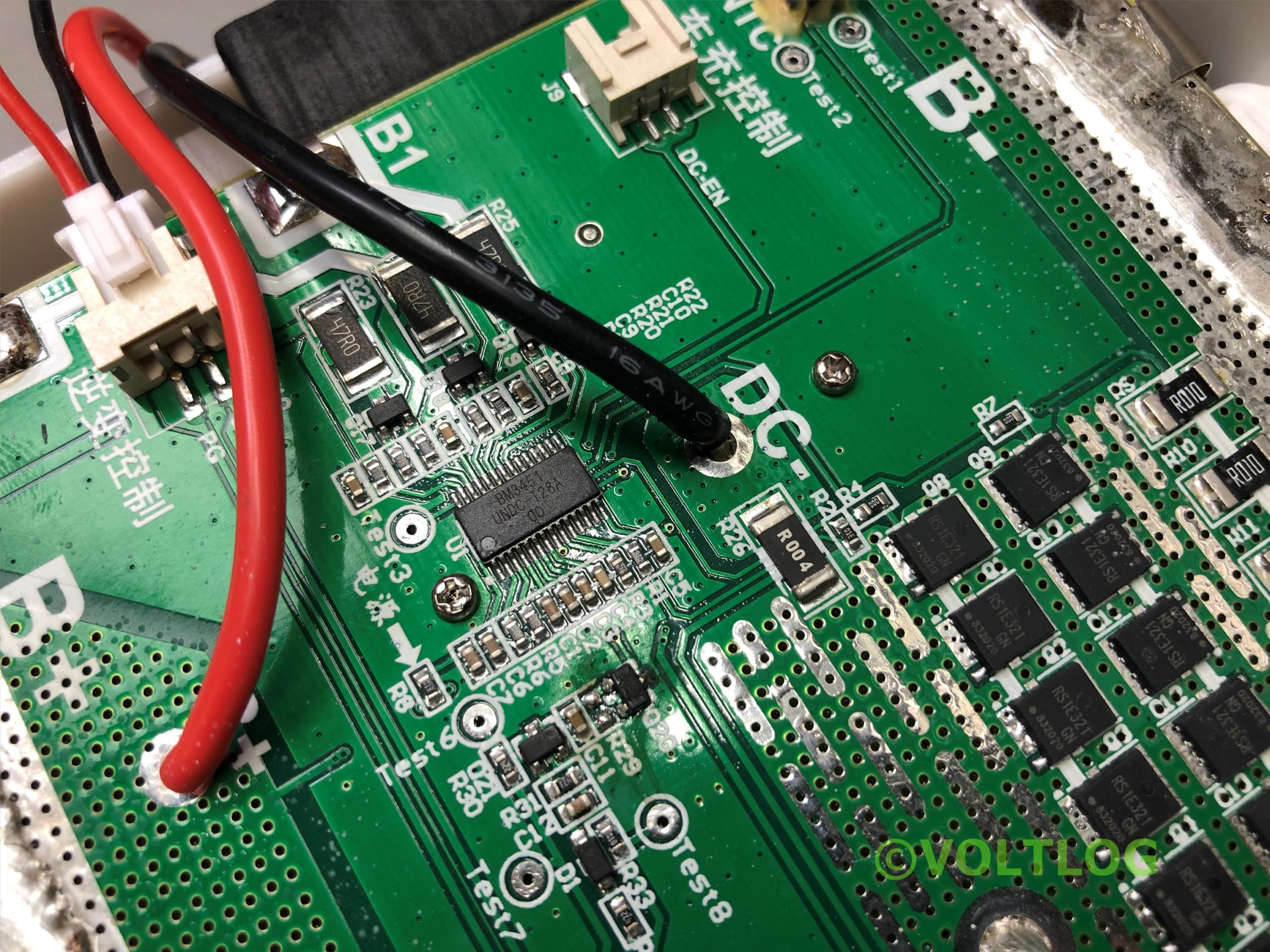
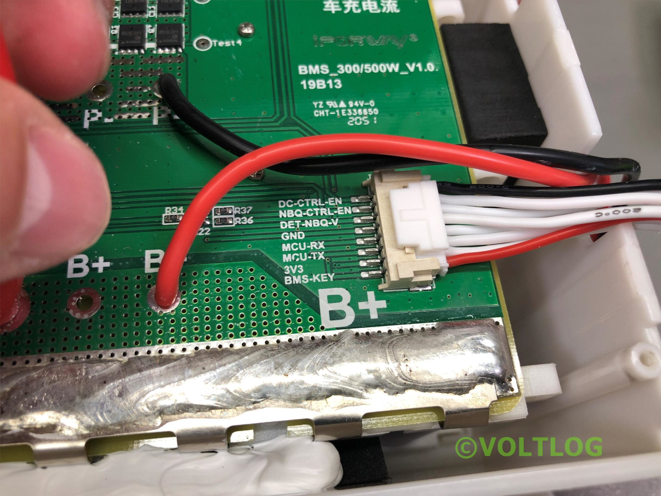
I’m gonna start the video with this lithium ion battery charger. If you remember this cheap cordless drill which I reviewed in voltlog 285, maybe you can remember that it had a pretty low cost battery charger which I sent to the DiodeGoneWild youtube channel for a teardown. So ever since then I’ve been charging this on one of my bench power supply units which is not very convenient because I can’t take it with me everywhere I go. So I’ve started searching on Aliexpress for a little more quality in one of these adapters and after many tries, I’ve found this model which doesn’t have any indication of being higher quality other than being different and slightly more expensive than other listings so I said why not give it a try, do a quick teardown to see how it’s built, maybe I can find something better that can also work as a recommendation for other people looking for something similar.
My next item is yet another Power supply unit, this time, it’s one that has all of the regulatory approvals and it should be of higher quality coming from meanwell. This is a 12V 2A, so 24W total, model number is HDR-30-12 and the main feature of this is that it’s DIN rail compatible and I plan to use this at some point to further expand my home automation project with some solenoid valve control. I’ve bought mainly to evaluate the quality. I haven’t yet decided if I should use 12V or 24V, also depending on the type of valves that I will be using but generally speaking 24V would be nicer because it could transfer energy more efficiently over the wires that I’ll be using. This is DC output so again, depending on the type of solenoid valve, those might require AC power so I might need a different power supply for that but when I bought this I was really thinking of using it with my servo project which needs DC power. Either way it’s going to be a useful power supply to keep around.
Welcome to a new video, today we’ll be taking a look at a device which I believe is gaining more popularity, especially as summer time approaches and people are spending more time outdoors. It’s no secret that we are dependent on our gadgets now more than ever and we need to keep them charged.
Regular 10-20Ah powerbanks can save the day for your phone or tablet but if we’re talking about multiple gadgets like multiple phones, tablets, laptops, portable speakers, lights, etc then you need something more serious with higher capacity, multiple ports, maybe even an AC outlet.
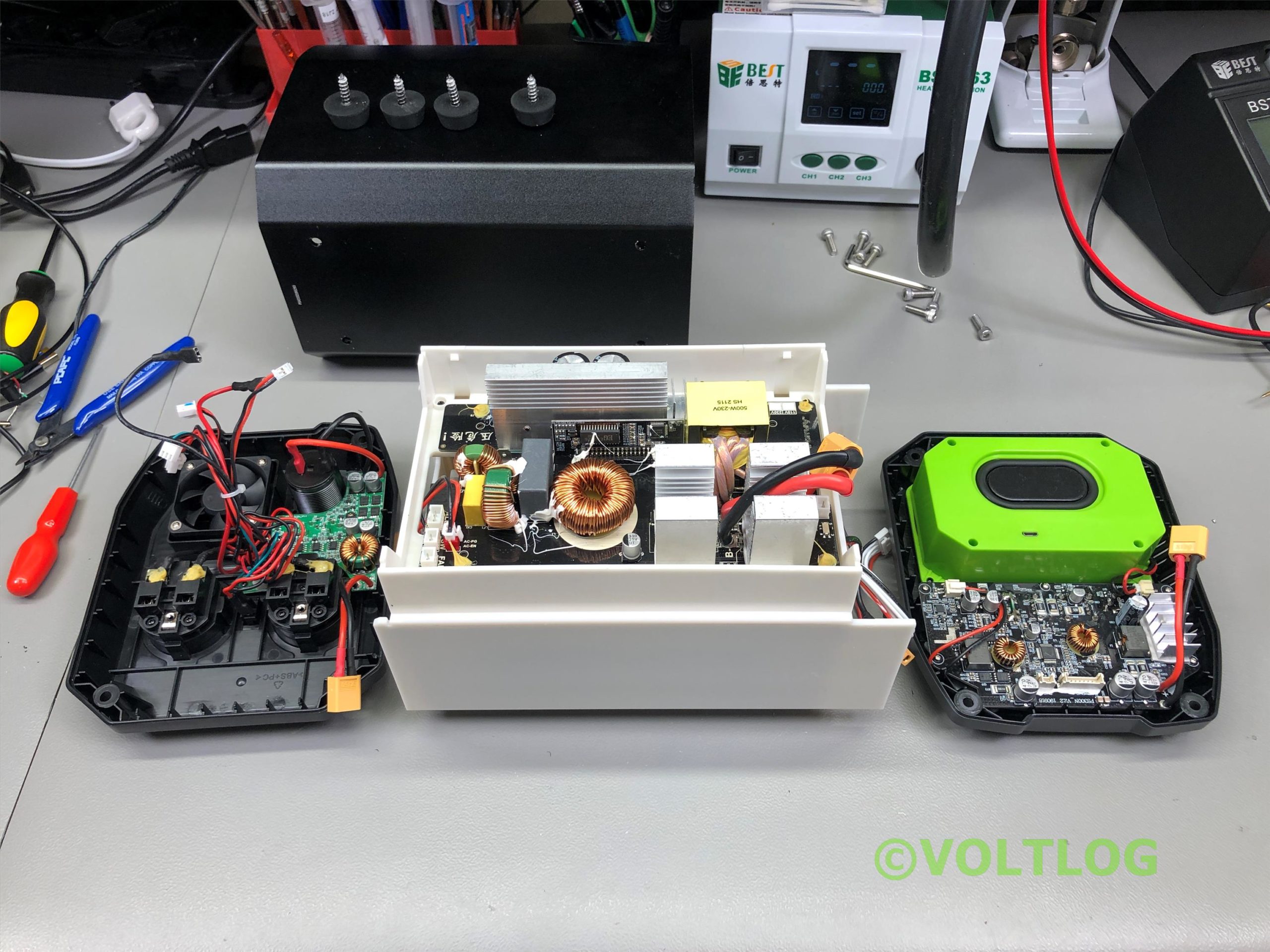
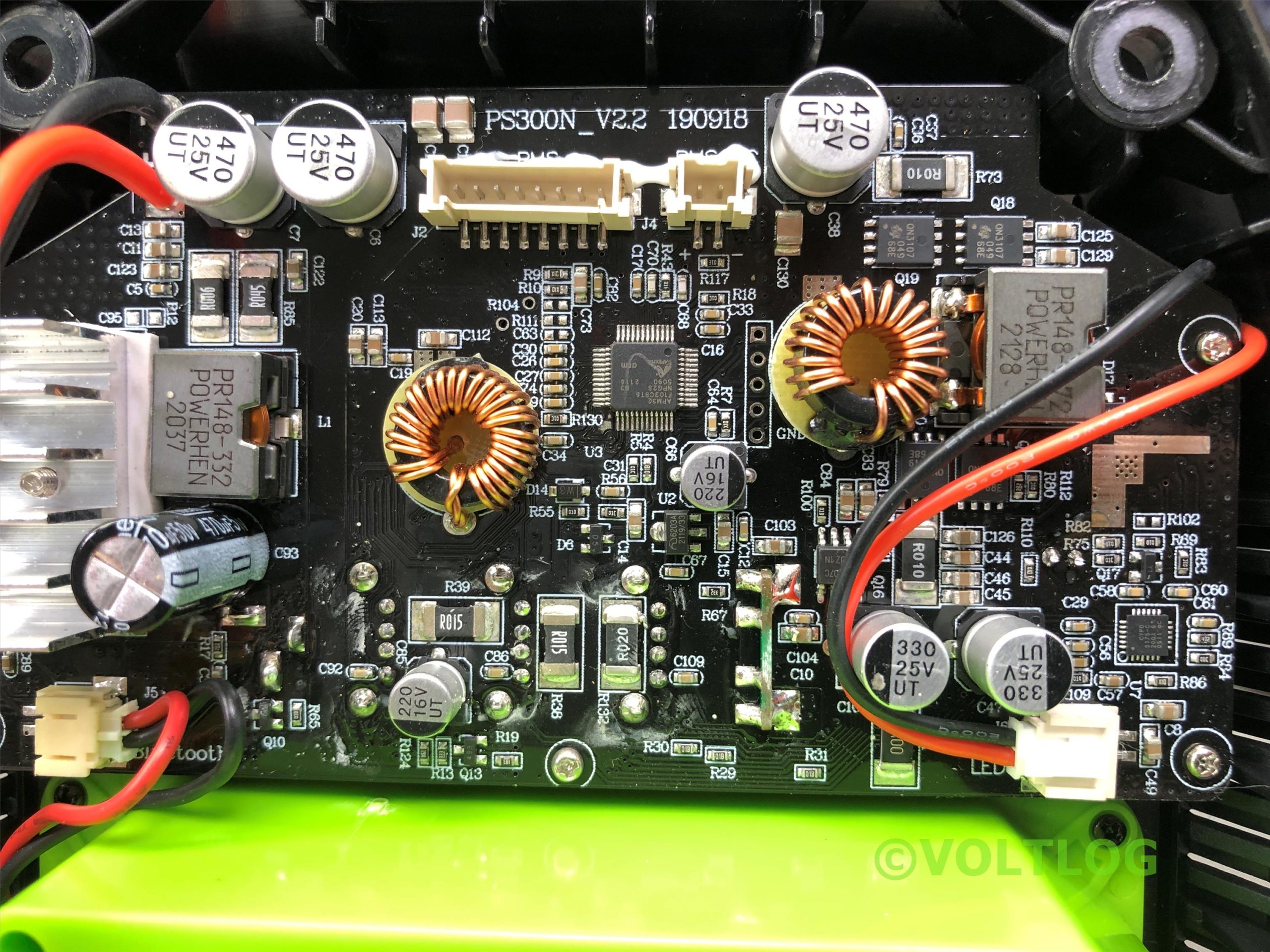
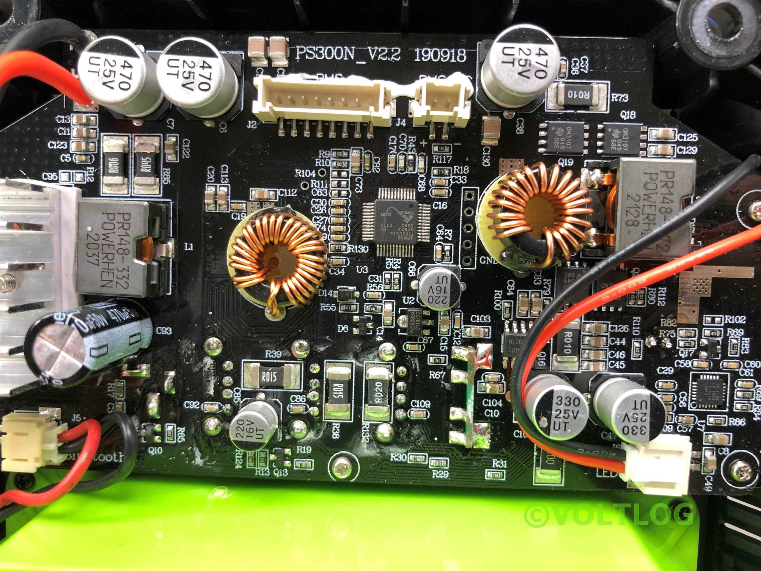
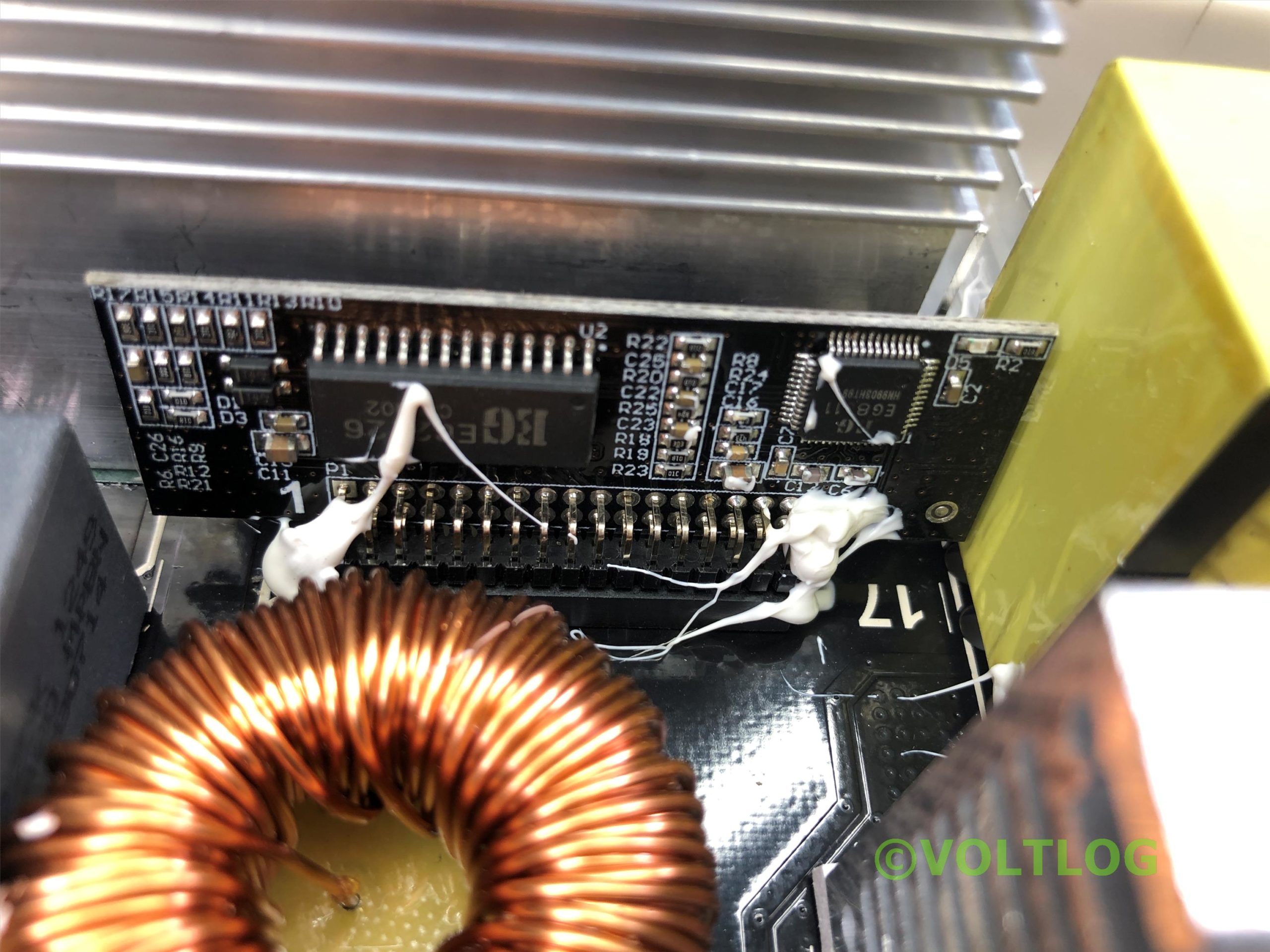
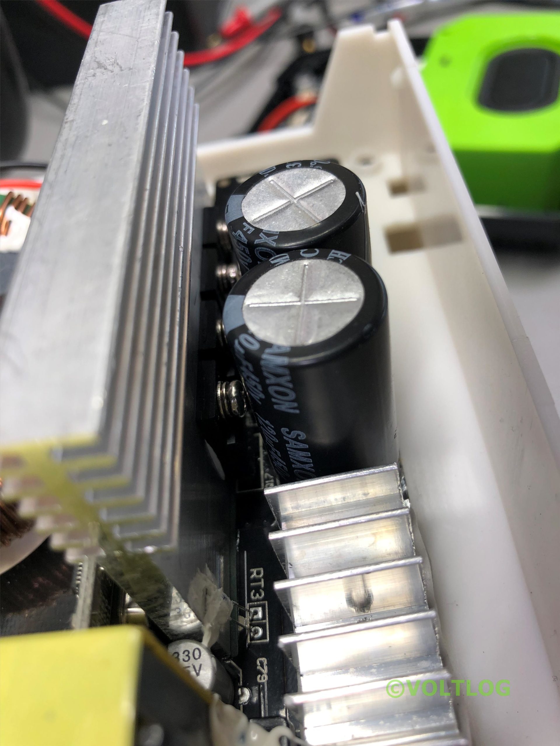
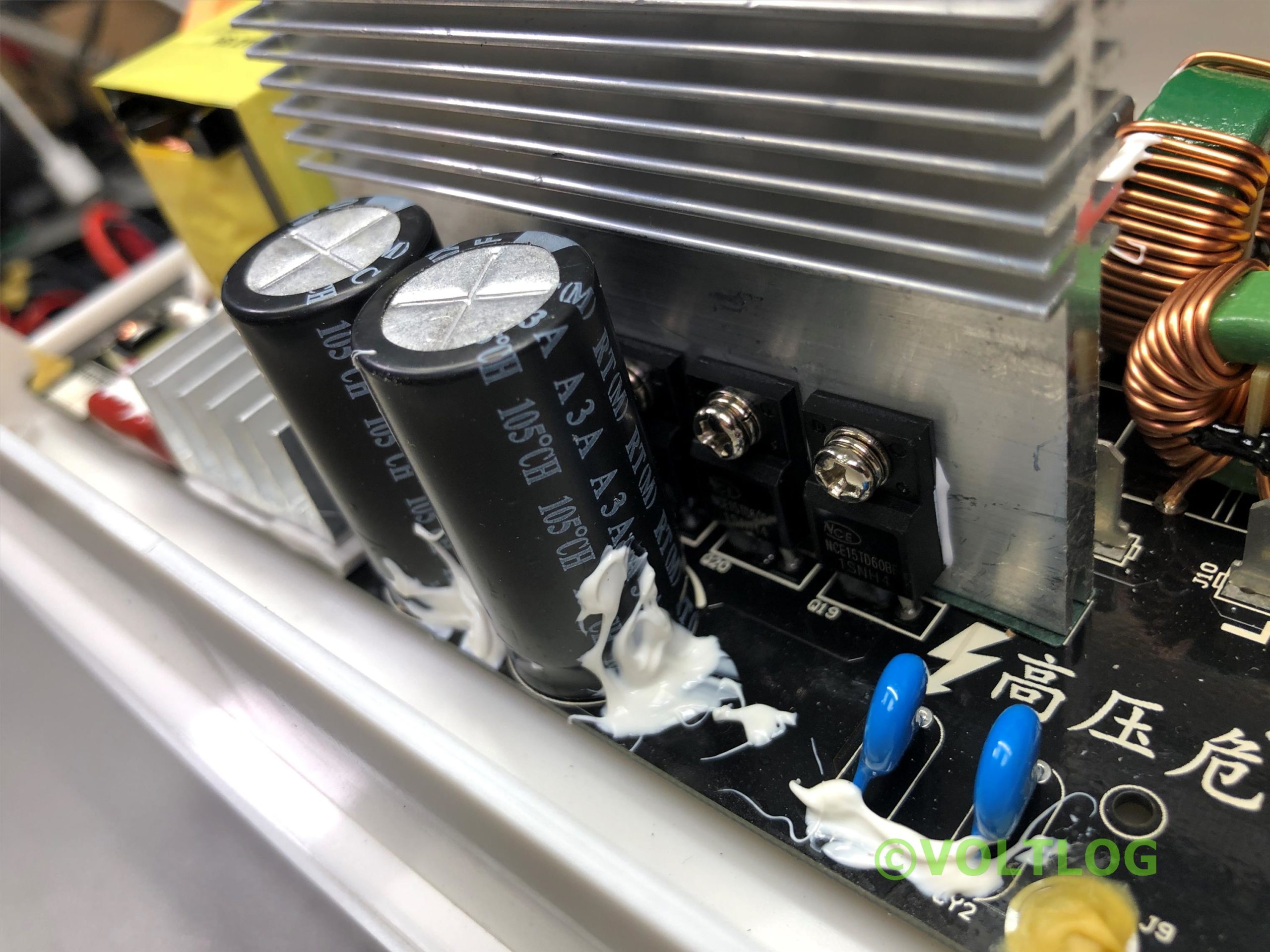
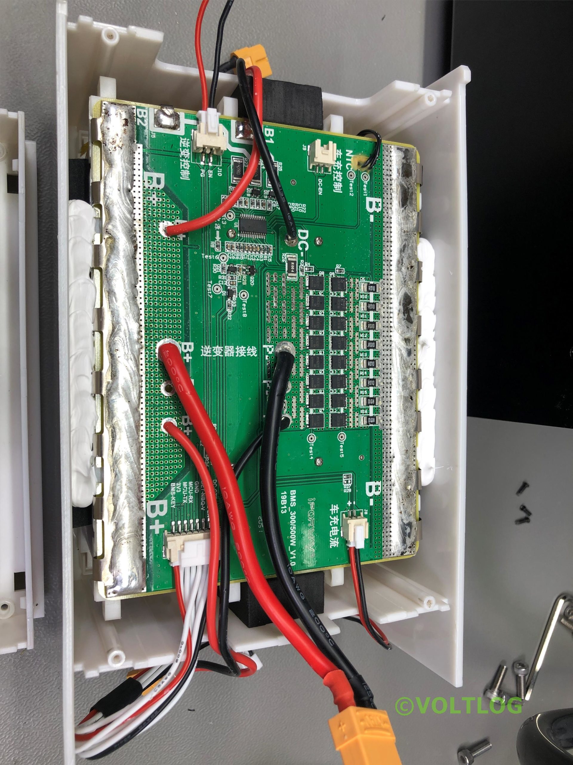
That’s why today we’ll be looking at this guy, it’s the Blitzwolf PG1 a true power station holding 124Ah of battery capacity(in this version which is the upgraded one) and providing you with multiple USB ports for DC output, two AC outputs, a built-in bluetooth speaker, an LED light with everything built into this nice rugged case which comes with a carry handle so this might be a true companion for a camping trip or a summer beach day or even for those unexpected long power outages.
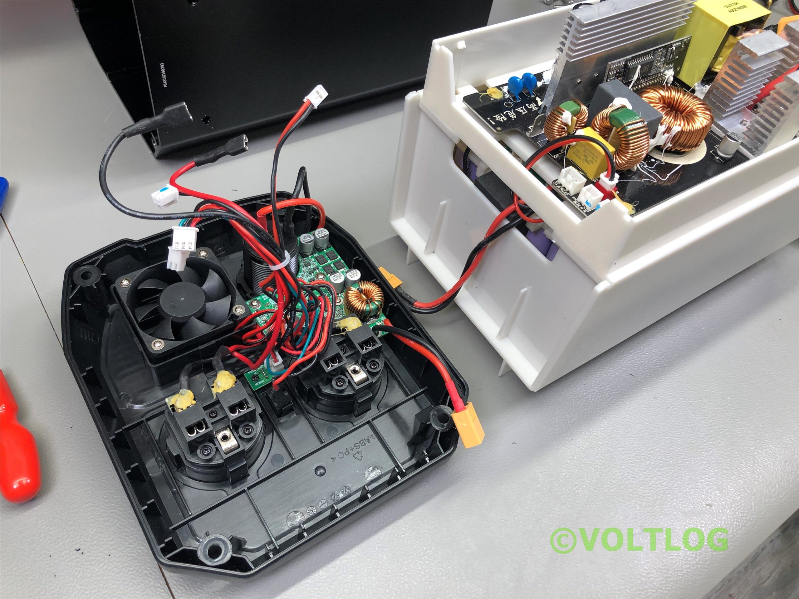
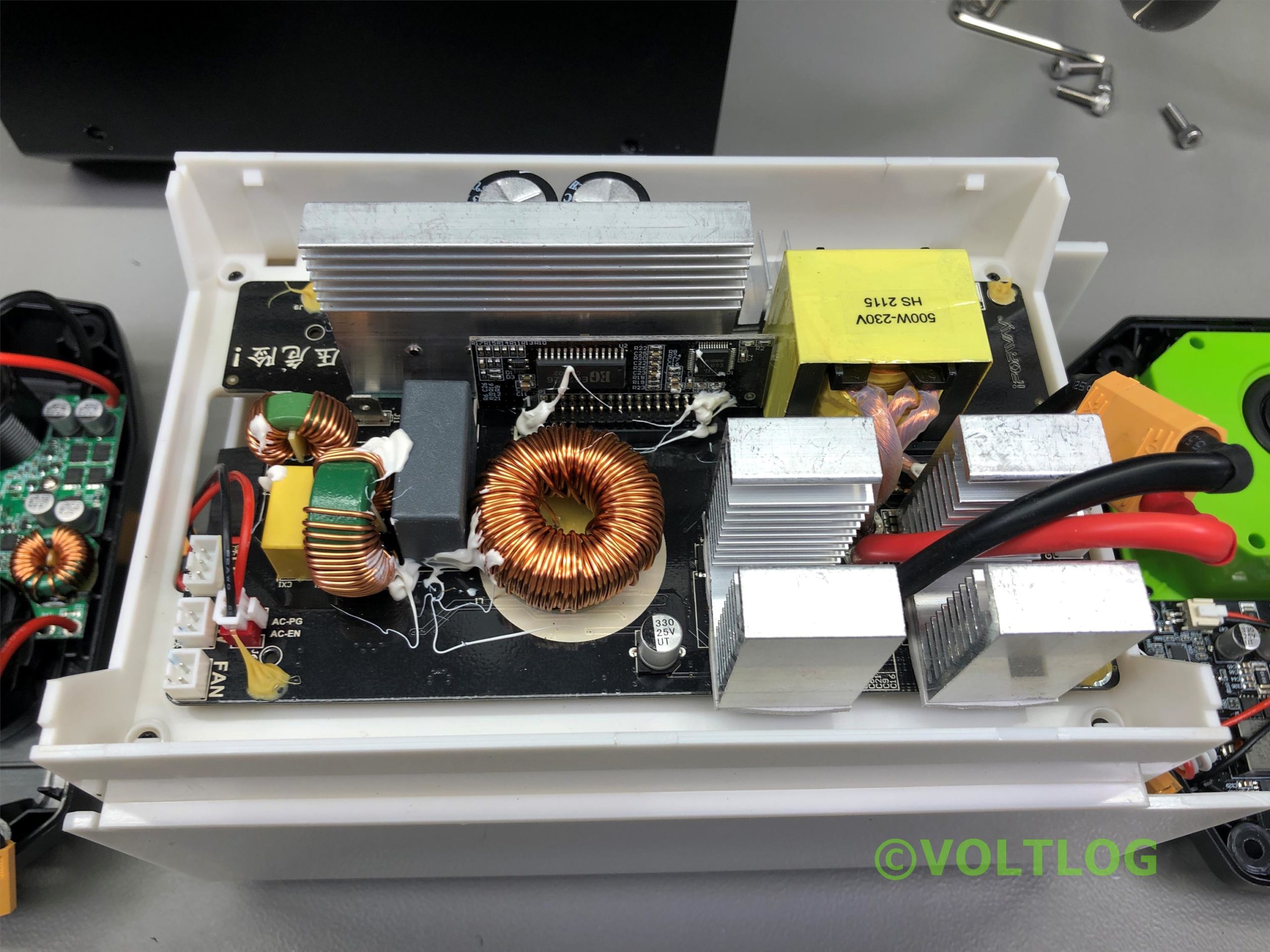
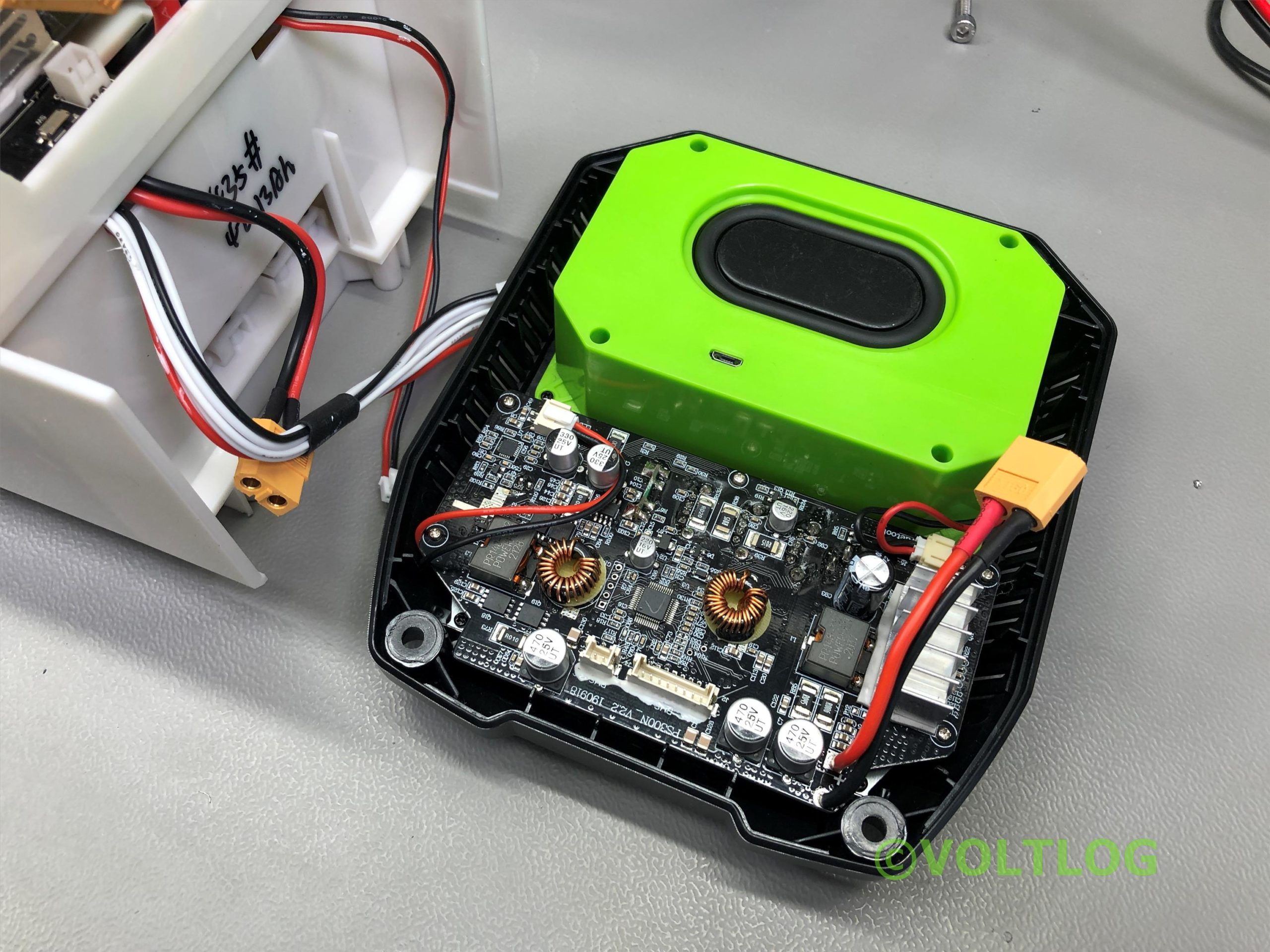
So everything sounds good on paper for this power station and blitzwolf products are generally pretty good. I’ve owned several power adapters, usb charging cables and various other smartphone accessories from Blitzwolf in the past and they’ve been great. I would say they are similar in quality with Baseus products if you are familiar with that brand which I also show a lot on this channel. But in this video we’ll check for ourselves, we’ll do a teardown, because having all of that energy inside this power station can be dangerous if it’s not built with a certain degree of quality and attention to detail.
The unit was super nicely packed in a thick double box so it arrived in perfect condition and its own internal packaging and protection is very professional so I don’t think anything can happen to this product during shipping but it’s also not wise to underestimate what shipping companies are capable of.
So I looked around for a portable Geiger counter that might give some indication or warning if the radiation levels start to increase. There are a few models available online, some which are for professional use but ofcourse you would expect those to be very expensive, so I was looking for something on the affordable side of things.
This model popped up in my searches, is the JD-3001 multifunctional Geiger counter and this can monitor gamma beta as well as electric and magnetic fields all in the same unit. I’m gonna put the specs of the unit on screen while I mention that it was offered for free by banggood.com for the purpose of this review and right now there is a high demand for these, but it shows in stock on banggood.com, the price is discounted and on top of that if you look in the description of the video you will find a coupon code that will provide you with an additional discount for this product.
Not sure how relevant it is but the unit also includes a temperature + humidity sensor which is located in this small extremity. When compared to other units available on the market this one seemed more interesting because it had some nice features like built-in lithium battery, rechargeable via USB Type-C port. It can do data logging on its internal memory and then you can access and download the logs through the USB port and probably the nicest feature is this big crisp color LCD display.
Welcome to a new video, this will be a review & teardown of this power profiler device so this can be useful if you are trying to measure the power usage of a particular board that you are working on. It can internally generate an adjustable voltage power supply rail which it outputs on these terminals, you use that to power the device under test then by using the supplied PC software you can analyze the power usage of your device in great detail.
As you may remember I also have a Joulescope which is an awesome piece of equipment, high resolution, high dynamic range for doing the same kind of analysis but it does not include the power supply. This guy with its included power supply is closer to something like an otii arc, cause that one also include the power supply so I might make some comparisons in terms of specs with these devices during the video.
Inside the box you get a power brick which feels low quality, a mains IEC cable with an adapter for European plugs, we won’t be needing these as I can use my own IEC cable with the proper plug, and a set of short test leads with banana plugs and J clips, The cable feels nice, flexible but the connectors are of low quality and you are likely to encounter problems if you will be using this types of clips long term so I will be replacing these as well. In my opinion, instead of including cheap test leads, you might not include any at all. Saves the final user the trouble of dealing with bad test leads.
The front panel features the two output banana plugs widely spaced apart, two rotary encoders crammed together and a couple of 7 segment displays for voltage and current so that you can get readings independent of the PC app. On the back we get the DC 12V input and the USB connection for the computer plus an on/off switch. They had plenty of space on the front panel so I think it would be nicer to have the on/off switch on the front. And the two potentiometers spaced wider apart. The model number for this unit is EMK850S+.
They don’t tell much in terms of specs but they mention Input Voltage 12V DC, Output voltage 0.5-12V,
Measure Range: 0.1μA – 2A, provides μA resolution current measurements with a sample rate of up to 10 ksps. No claims on accuracy as of now but maybe they’ll add those later, as I said this is a new product. If we compare it to the joulescope which has a 2Meg sample rate and 1nA resolution the TechRejoe unit is clearly lower specced but also less expensive
Ever since I’ve started offering the option for the Shelly programming cable, lots of people have ordered one because it makes the job of flashing an otherwise dangerously mains connected relay very safe by not having to power it from mains, but just supply it with DC power from the VoltLink itself.
But this video is not about that, it’s about the latest revision D of the board, the changes that it contains and some future plans.
So as you may have noticed there is no power LED on the VoltLink and to be honest for my personal use case I don’t really need one but I do understand people that want a power status LED so that they get a quick glimpse of whether the board has power or not.
Personally I think that because the VoltLink is so reliable in operation, the power LED is redundant but I do remember the times when I was using other cheap usb to serial adapters, there were the occasional issues with the micro usb connectors failing, with the on board chip failing, so it was nice to be able to see that you still got power to the board at least. Nonetheless, I added one to the new revision, placed it right next to the USB connector.
Now because I added these two extra components to my schematic, the LED and the resistor, I decided to switch to a resistor network to replace 4 x 1kilohm resistors with a single package to further optimize my BOM cost and DFM.
Another small change I did was to bump the 4.7uF decoupling capacitor on the USB to serial chip to 10uF because I was already using that value at the output of the voltage regulator. This once again, optimizes my BOM for using less parts as this will become important later.
And while I was revising the PCB, I also switched to these nice labels created with the Kibuzzard plugin for Kicad. No extra functionality because of these, but they do look nice.
Welcome to a new InTheMail, the most popular segment hosted here on the channel and for today I have lots of really cool gadgets to show so stick around for that.
I’m gonna start the video with this Xiaomi / Honeywell Smoke fire alarm sensor. Obviously Honeywell is a very well established brand when it comes to sensors so Xiaomi partnering with them totally makes sense. There are a bunch of different variants for this sensor available on the market. This one in particular is model number GD-03MI/BB and this is a bluetooth sensor. I wanted a zigbee sensor but I couldn’t find it in stock with Banggood so I had to go for this bluetooth one, it shouldn’t be a major issue as I have bluetooth connection on my homeassistant server as well. That’s the plan to connect this via Bluetooth to homeassistant so that I get smoke alarm capability via HomeAssistant.
You could also use this with a Xiaomi gateway and get the notifications in the Xiaomi app but I prefer to use HomeAssistant and this device seems to be supported by the Passive BLE integration which should automatically discover it. This sensor uses a CR17450 lithium battery which is not that common and they tend to be more expensive because of that, luckily it does come with an included battery which should last up to 5 years according to the datasheet. I would be happy even if it lasted just 2 years and would consider anything above a bonus.
I have yet to test this, I will be running some tests after installing it but I can tell you that it also provides local light and sound alarm so you don’t need to rely on having it connected, it will sound it’s 80dB buzzer when smoke is detected and just considering that it uses Honeywell sensing technology with the higher quality of Xiaomi products, this has to be more reliable than the no name brands that you can find online so if you are interested in getting one, there will be a link provided in the description below.
Welcome to a new video, this will be part 1 from what I expect to be a 2 or 3 part series where I show you how I designed and manufactured an automation for controlling the main water supply valve in my apartment. The first part will be related to the mechanical construction while the second part will likely be related to the electronics needed for control.
So first of all the reason why you might want to automate this is for protection in case of failure, you can detect the water leaks using other sensors and close the main valve to prevent extensive water damage. You might also want to conveniently turn it off remotely if you go on vacation for extended periods of time, stuff like that.
Now you might say there are ready made solenoid valves that run on various voltages and you can use one of those to replace an existing analog valve and at that stage you would just need a relay to turn power on or off to that valve. And that is certainly a good option for those that are building a new installation, you can certainly plan for that and install one of those solenoid valves but in my case, I would need to shut-off the building main water supply and get a plumber to install that valve which I would like to avoid. I am also aware of servo type accessories that clamp over existing valves but seem to be designed for the lever type valves so they wouldn’t work for the style of valve that I have installed.
So the first step for me was to get a spare valve, needed it to be the exact same model, luckily I could find an identical one, it’s from this company Herz Austria so now I could take measurements of this and recreate a 3D model in Fusion 360. I could not find a 3D model for this specific model from the manufacturer so I had to recreate this but it didn’t take too long because I was only interested in the rough outside dimensions and not the intricate details on the inside.
You would think that implementing USB Type-C Power Delivery protocol on your upstream facing port is a difficult task and if I would ask you if you can also support Qualcomm quick charge on top of that, the issue is even more complicated and you would probably be right to think so if you wanted to implement all of this by yourself but luckily you don’t have to, because there are dedicated chips that can do all of this and in this video I’m gonna show you how to use them.
So recently I started working on a project which needs USB Type-C Power Delivery input for negotiating 5 and 12V, it would be nice to also support Quick Charge, I basically need the capability to power my board from a standard phone charger with either Power Delivery or Quick Charge support. This will be an open source project, but I’ll talk about it in a future video after I build the first prototype.
Now to understand more about USB Type-C and the different power roles like Downstream Facing Port, Upstream Facing Port or Dual Role Port I suggest you check out this neat application note from TexasInstruments which is called “a primer on USB Type-C and Power Delivery” I will put a link to this in the description below and if all of this is new to you, it will help you understand how things are organized under USB Type-C.
What I need is the ability to sink up to 3A with 5V or 12V selectable voltage levels into my board, so that fits under an Upstream Facing Port definition and I wasn’t going to start implementing the power delivery negotiation protocol, it’s just not worth the effort when there are chips, specifically designed to do that. After a bit of research I have identified a company named Legendary Technologies from Shenzhen, they seem to specialize in building these chips that provide USB Type-C negotiation for various roles. I have contacted them and I’ve been in touch with one of their applications engineers, they’ve been very supportive and have provided me with samples and support for implementing their chip which is very nice. I appreciate that kind of support and it helped me decide to use their chip in my design.