JTAG Adapter PCB 20pin 2.54mm to 10pin 1.27mm – Voltlog #347

Welcome to a new Voltlog, this will be a rather short project video, I thought I’d start the year with something simple. If you’ve ever used JTAG before, either to program or debug an ARM processor, or something like an ESP32 or maybe to load a bitstream into an FPGA, you’ve likely encountered the ubiquitous 20 pin JTAG connector which is this 2×10 0.1inch spaced connector. It’s a rather large connector, it takes up a lot of space on a PCB, you don’t really need that many pins but you can’t go without it because it’s usually present on the fully featured programmer/debugging tools. Here is an example: this is an ST-Link V2, or to be precise a cheap clone from aliexpress but for the purpose of this discussion it doesn’t matter, it looks the same as the original and it has this 20 pin JTAG connector. 

And to some extent this isn’t really a problem if you are using big development boards like this STM32F4 dev board that I got from Aliexpress. This features the same 20 pin connector for programming so it’s a matter of connecting a simple ribbon cable and you’re up and running. However, most modern boards that you are going to be designing might not have enough space to install such a big connector, you might for example use the simpler 10 pin JTAG connection, cause you don’t even need that many signals, most of the pins are GND anyway on the 20 pin connection. And instead of using 2.54mm pin header you can use something smaller like half the size, 1.27mm, and this can save a lot of space on a board.
Why Did I Get A New 3D Printer? Ender 3 Pro | Voltlog #312

If you would like to hear why I switched from the Creality CR10 to a Creality Ender 3 pro join me in this video, I’ll share the reasons for which I made the switch as well as talk about the improvements Creality made to the standard Ender 3 to become the Ender 3 pro. But first, let’s do the unboxing.

Inside the box everything is well packaged and protected with foam but compared to the CR10, the Ender 3 is less assembled to say so, there is more assembly work for us to do, if you are in a hurry that might be an issue but for me I actually like doing a bit of assembly work on a new gadget.

While doing the assembly I took a look at the supplied sd card and I also found an assembly video with english captions, it was well made and easy to follow. There are two extra steps I did during the assembly, #1 was to take off the power supply protection cover and made sure all connections are nice & tight and the voltage selection switch is in the right position #2, the lead screw comes already greased but in my experience with the CR10 that type of grease will attract dust on the lead screw which will turn into this black gunk over time. So I cleaned the existing grease with some isopropyl alcohol and a toothbrush and at the end I applied some dry PTFE lube to the lead screw which in my opinion is better suited for this application.

Voltlog #145 – How I Failed To Install Auto Bed Leveling On My Creality CR-10

In this video I was supposed to upgrade my Creality CR-10 3D printer with an auto-leveling sensor but I failed to do that and I will explain why in a few minutes. 

The upgrade would involve showing you how to connect the sensor to the motherboard and then flashing the open source marlin firmware to add the auto-leveling features as well as other improvements.

The thing is, nobody tells you that you can’t have the SD card option, the graphical lcd option and the auto bed leveling option active in marlin firmware at the same time when compiling for the stock CR10 board with the atmega1284 which only has 128K of flash memory. The resulting program will simply not fit on that 128K of memory.

Here are links to the stuff mentioned in the video:

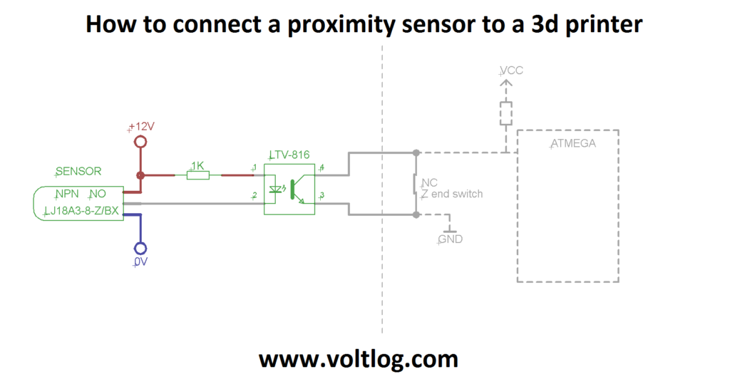
Here is how to connect the sensor to your 3d printer using an optocoupler