Choosing, Placing and Routing A Shunt Resistor | Voltlog #313

If you are looking for the correct way to select, place and route your current measuring shunt resistor on a PCB then stick around as I will be sharing a bunch of tips & tricks that I learned while designing and building my own boards over the past years.

A shunt resistor can be used in multiple ways but for the purpose of this video we are interested in using it for measuring current, this means it needs to be inserted in series with the device under test. It can either be inserted in a high side configuration as shown in this example but it can also be inserted in a low side configuration. These two typologies have their advantages and disadvantages.

Here is a side by side comparison, when used in a low side configuration there is a ground offset which depending on your application may or may not pose problems. When used in a high side configuration, you must use a differential input amplifier for sensing the voltage drop while in a low side configuration you can get away with single ended.

Another thing that might be important, in a high side configuration you have the ability to detect a short on the load, while on the low side configuration you can’t do that. Also in a low side sensing configuration, you are not able to sense and account for additional leakage currents through stray secondary paths from the load to ground. This list might not be complete, there might be other differences to consider, these are just the ones that I had to consider in my designs.

But let’s say you’ve figured out the topology you want to use and you are now faced with choosing your current shunt resistor. Can you just pick your typical metal film 1ohm resistor from your favorite distributor? You can, but you won’t get the best results. Probably the most important factor you want to consider when choosing your shunt resistor is the temperature coefficient or the temp co as engineers like to refer to it. This will tell you how much your resistor value is going to change with variations in temperature. 

Every system you build will probably see a variation in temperature at board level and so if you calibrate your system to calculate the current for a given resistor value and that resistor value changes with temperature, you are going to introduce significant errors in your measurement.
ScopeShunt Visualising The Current Waveform With Your Oscilloscope | Voltlog #310

We usually use an oscilloscope for visualizing a voltage over time but sometimes it’s also useful to visualize the current waveform over time. The right way to do it is to get a current probe which can sense the current and convert that to a voltage that the oscilloscope can display however such devices are pretty expensive, they can be around $1000 even for an entry level one like the Rigol RP1001C which is only rated up to 300KHz bandwidth.

But we can improvise something for a much lower cost and it should allow us to visualize the current waveform on the oscilloscope. You’ve probably seen me use a shunt resistor when testing power supply to take a look at the current waveform. Because as you know passing a current through a resistor will generate a voltage drop.

That voltage drop is directly proportional with the passing current and with a round value resistor we can have an easy to use transformation ratio between voltage and current. All we have to do is o introduce this resistor inline between our power supply and the device under test

For example if I have a 1ohm resistor, we have a 1:1 ration, for each mA passed through that resistor we will have  1mV of voltage drop that our oscilloscope can display. Such a circuit will of course have it’s limitations, for example it won’t work very well when testing low voltage low power devices because our resistor will introduce a burden voltage, which will drop our supply voltage to the device under test. This is also not an isolated measurement so it might not be safe when connected with higher voltage circuits.

But there are still a lot of scenarios where you could use this successfully on the electronics workbench so it might be worth building something like this. I want to make this nicer by building it inside an enclosure with the required bnc connector for connecting to the oscilloscope and 4mm banana plugs for passing the current through. I picked this small aluminium enclosure which would be enough to house the resistor, actually the resistors, because there are several advantages to using multiple resistors in parallel.

Alternative to this simple shunt resistor measuring method include the Joulescope which is a fully featured dc energy measurement test instrument with incredibly wide dynamic range that allows you to capture the smallest currents next to a jump to a higher current. I reviewed the Joulescope in Voltlog #211.

Voltlog #132 – 4 Digit LED Panel Meter Review

Do I recommend getting this module? Yes, the accuracy is good, the resolution is nice 10mV 1mA and you also have the option for adjusting it manually for both voltage and current.

The design is pretty simple, I believe the microcontroller is an STM8S so hacking it and rewriting the firmware should be pretty easy but it already does what it’s supposed to do so I don’t see a point to hacking this module. I think you would be better off designing a panel meter from scratch.

Buy this panel meter from here.

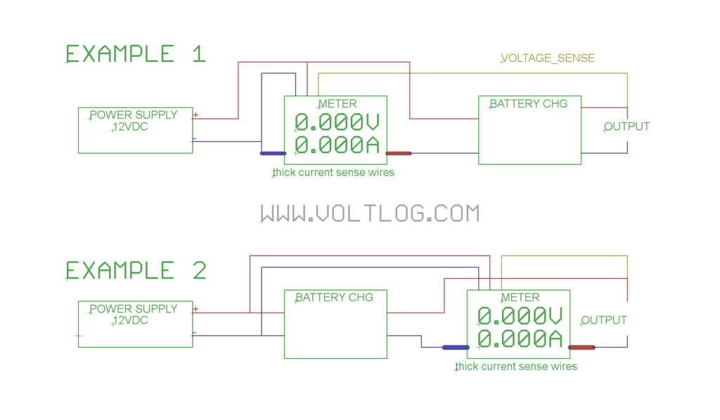
Someone asked on youtube how should a panel like this be wired up, so here is a wiring diagram that you can use. In this wiring diagram our goal is to monitor the voltage and current for charging a battery.

Example 1 shows the panel meter connected before the battery charging module, which means it will measure everything, even the power losses in the battery charging module.

Example 2 shows the panel meter connected after the battery charging module, which means it will only measure current flowing into the battery or whatever load you have on the output.

In both cases voltage sensing is done right at the output but that wire can be moved according to your needs. Also in both cases the panel meter gets power directly from the power supply because at that point the voltage is constant.

The main thing to remember here is that these panel meters are designed for low side current sensing, that means the ground of the logic board of the meter is connected with the input of the shunt resistor.

Voltlog #127 – 0-60V 0-10A 1mV 1mA Panel Meter Review

So I discovered this module a few months ago and it’s been sitting in a box since then, I almost forgot about it, until a few days ago when I decided it will be a good idea to do a video on the subject.

Let me give you a few details on the specs of this module and as usual it’s pretty difficult to find the information as it’s the case with every new module coming out of China. First of all we have an input range of 0-60V and 0-10A and a 5V rail is needed to power the module itself. It has a voltage measuring accuracy of ±0.2% + 0.2% full scale which sounds strange because these figures are usually given in a percentage plus or minus a number of least significant digits. The current measuring accuracy is ±0.4% + 0.3% full scale.

The meter is basically capable of measuring with a resolution of 1mv and 1mA (however the accuracy is quite bad, as shown in the video) which is quite nice and useful (not really useful with bad accuracy) for projects like DIY power supplies or DIY electronic loads. It can also display the power in watts with a resolution of 1mW as well as showing the load impedance.

Here are some links to this product: