Just a short video showing you the nicest pcb ruler I’ve seen so far. It contains the most common microwave components that you will find in an RF design.
Tag: RF
Voltlog #106 – InTheMail
Hello and welcome to a new InTheMail, this one is shot from the new Voltlog lab. I haven’t finished setting everything up in here so the sound & lighting might not be to the same level that I had before but please bare with me I’m working on solving everything. Since I haven’t installed all my equipment I thought it’s better if I do an InTheMail episode so let’s get started.
Here are links to all the items shown in this video:
- 90 Degrees Angled RP-SMA Male to Female Adapters
- SMA Male RG402 RF Connector
- RP-SMA Male RG402 RF Connector
- SMA Female RF Crimping RG58 Connector
- SMA Male RF Panel Mount Connector
- RG402 Rigid Coax Cable
- USB Type-C SMD Connector
- Dual USB 3.0 Type A Jack
- 3.5mm Stereo Jack Socket SMD
- 0.1 Inch Pin Header Different Colors
- Screw Terminal Connector 4 pin 5.08mm
- 3.5mm Stereo Jack Plug
- 3.5mm Gold Plated Stereo Jack Plug
- Panel Mounting DC Jack 2.1mm
- DB9 Female/Male Adapter Gender Changer
- 4mm Banana Jack Plug High Current M5
- 18650 Single Cell SMD Socket
- 18650 Dual Cell SMD Socket
- N/O SPST Reed Glass Switches
- Green SW-460 Tilt Switch
- SW-100 Tilt Switch
- SW-200D Vibration Switch
- SW-18010P Tilt Switch
- Mini Rocker Switch 3A 250V
- Round SPDT ON-OFF Rocker Switch 6A 250V
- Slide Switch SS12F32 SPDT 5V 0.3A
- Latching Flashlight Switch 1A 30V DC
- Blue Latching Push Switch 8x8mm 6 pin
- Momentary Push Button Switch
- Tactile 12x12mm LED Indicator Switch
- KSD9700 N/O Thermal Bi-Metalic Switch 50C
- 24AWG UL1007 Hook-up Wire
- 24AWG Silicone Wire
- Prototyping Copper/Silver Wire
- Vintage Color Braided Cable
- Heat Shrink Tube 27mm
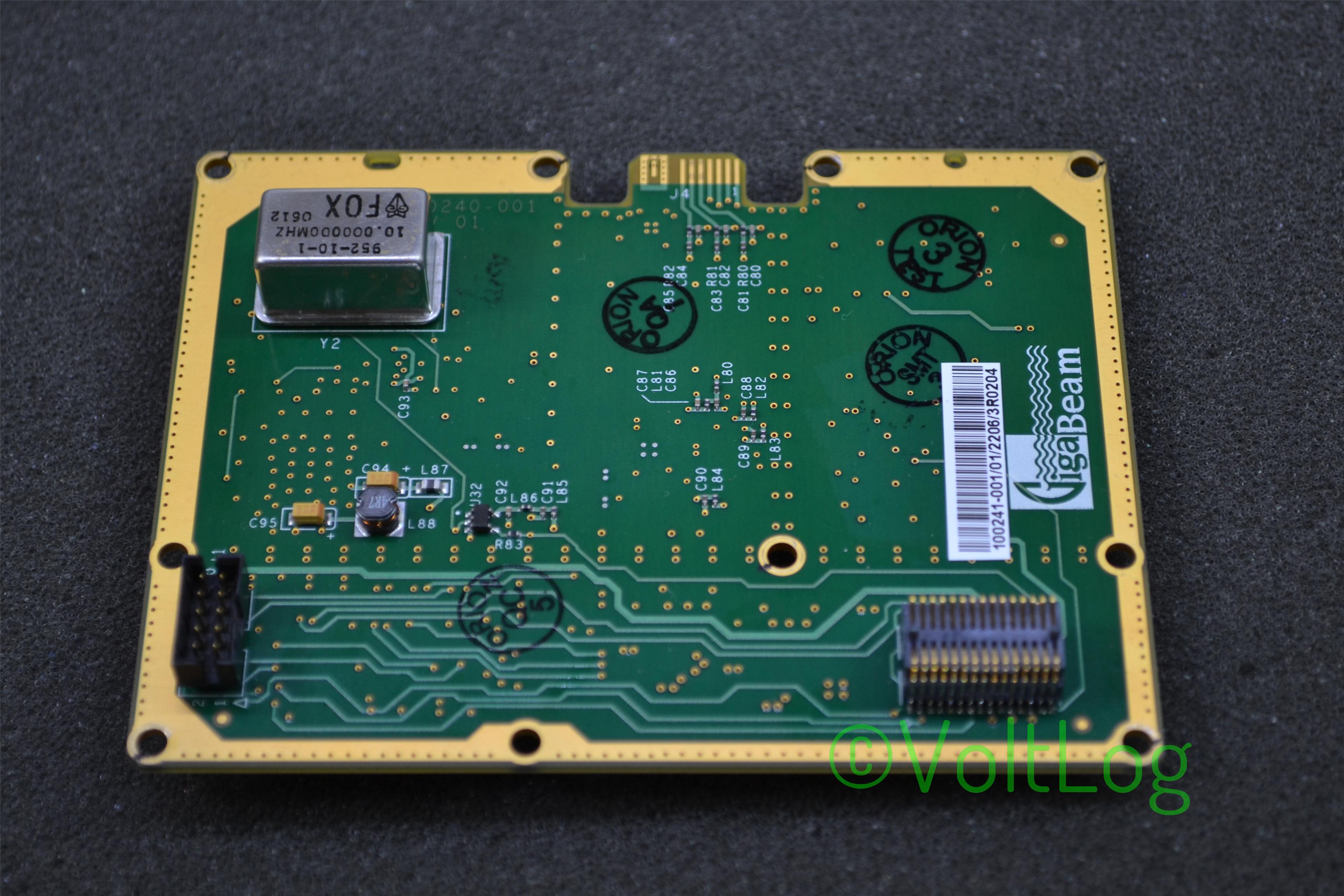
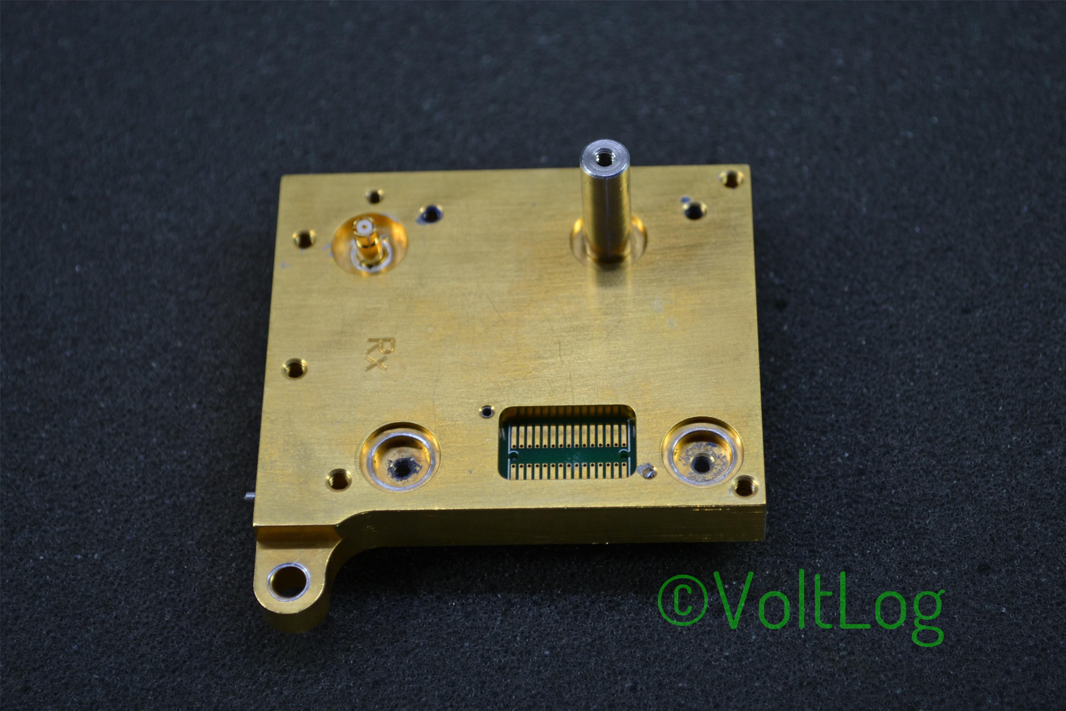
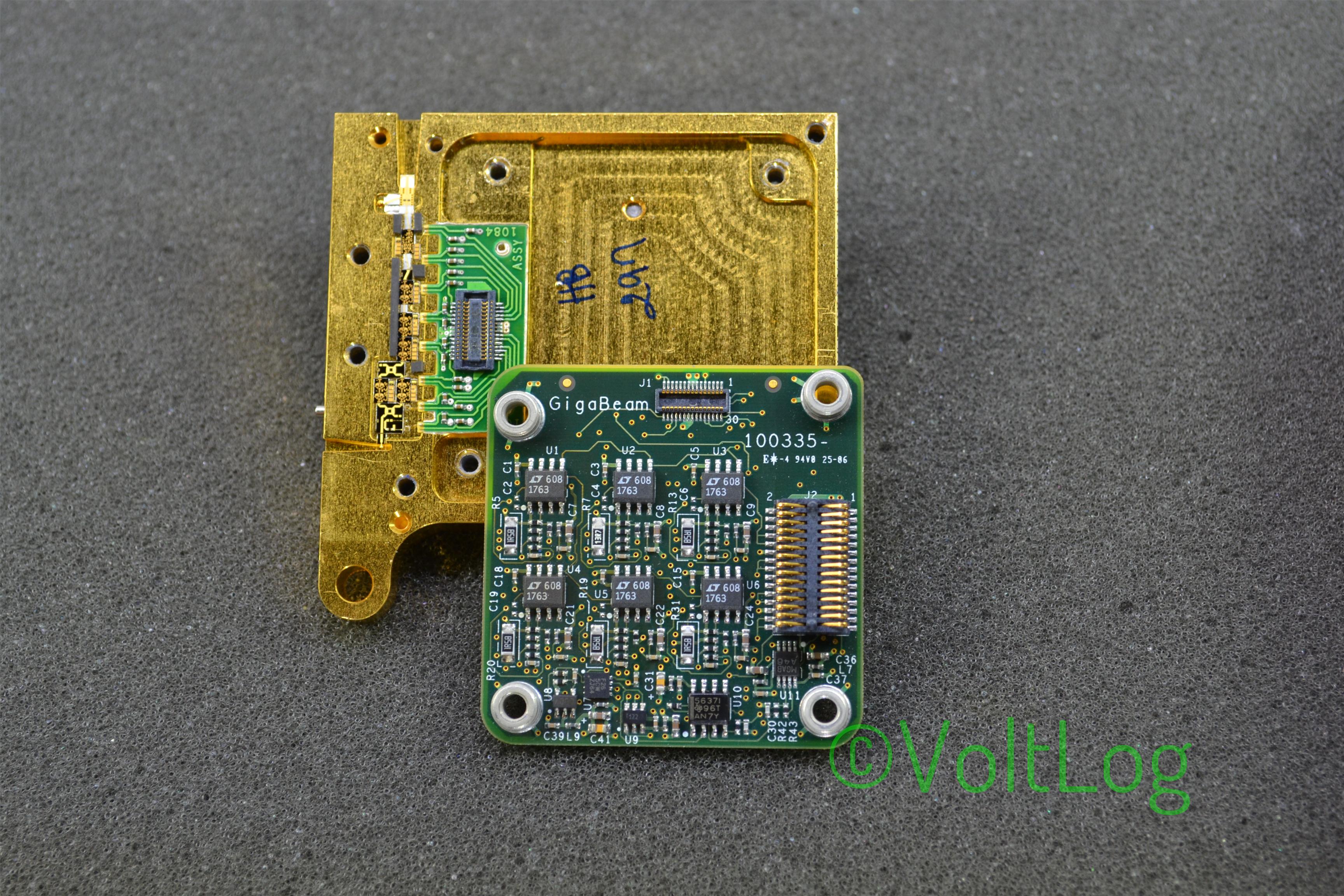
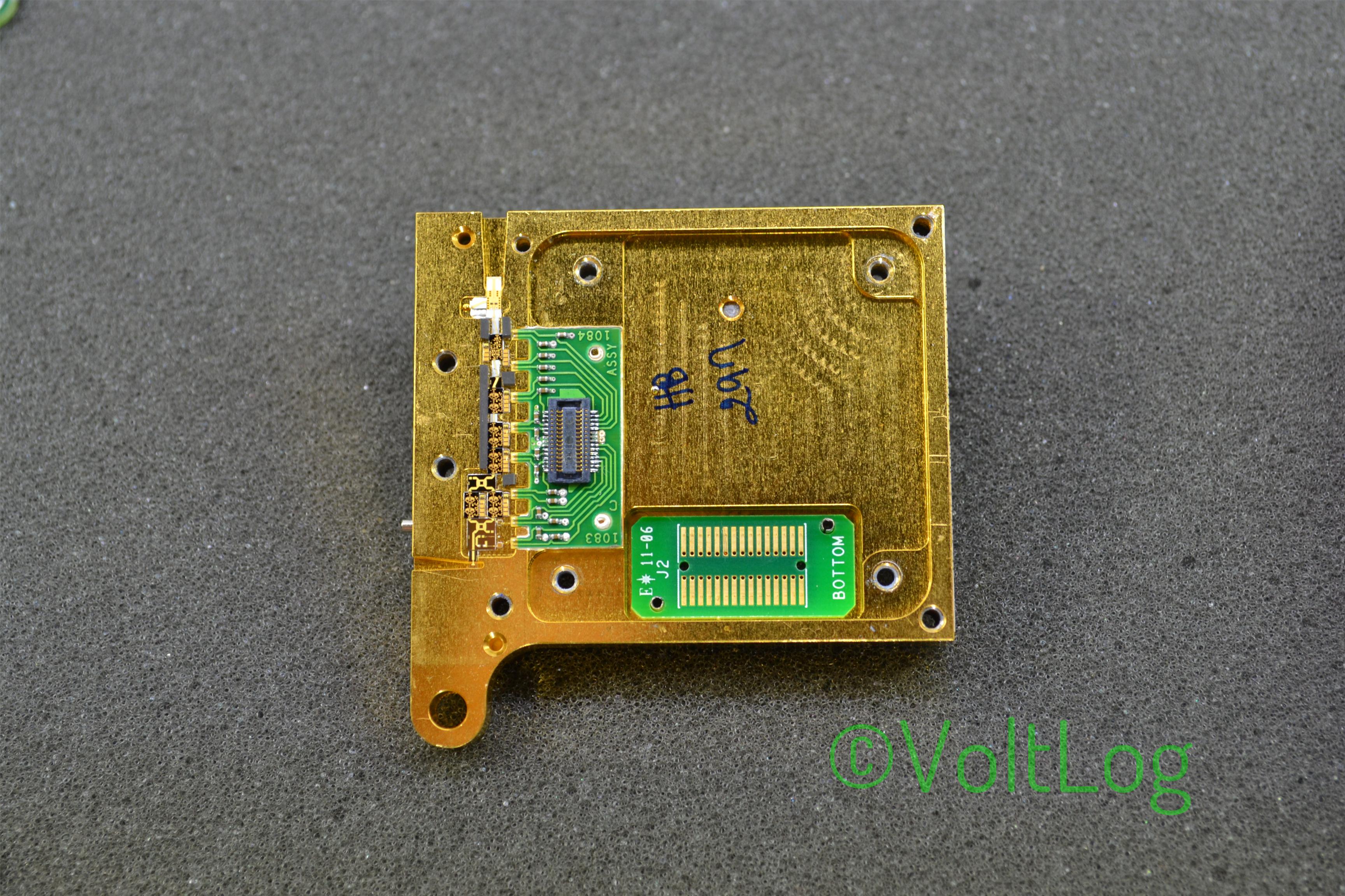
Voltlog #23 – Gigabeam WiFiber G1.25 Teardown
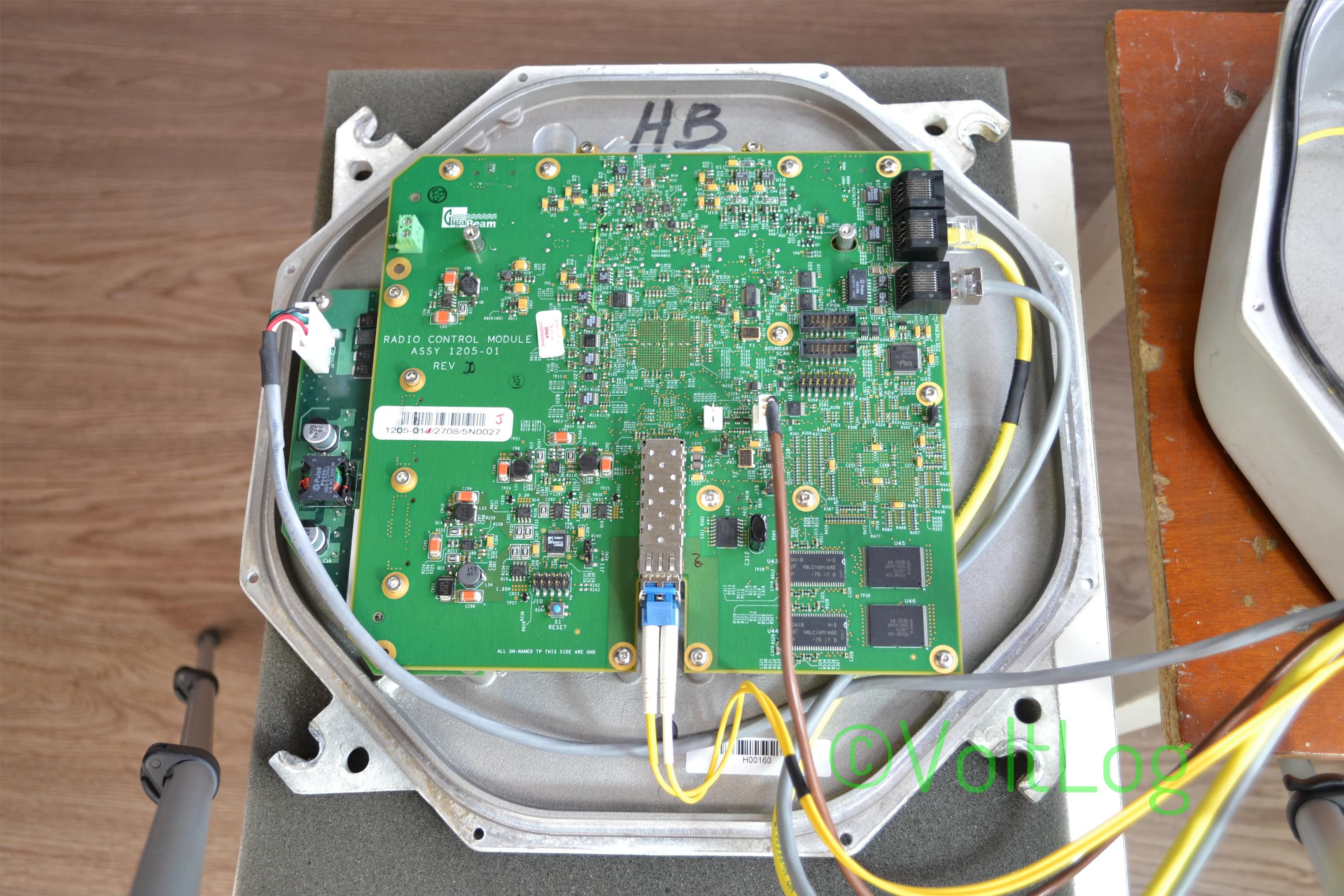
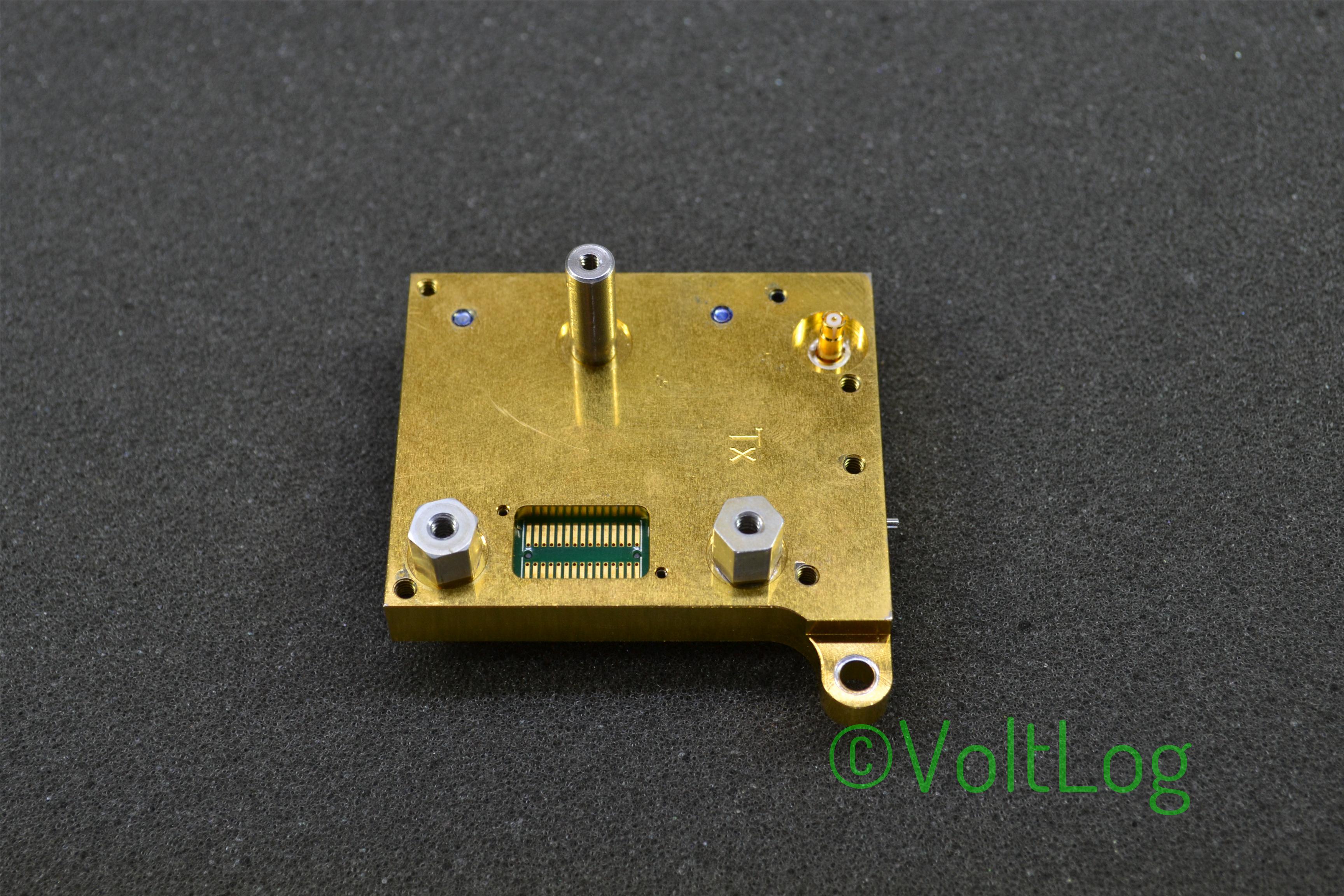
Hi, welcome to a new voltlog, today we’re going to teardown something interesting. As you can see on my left I have this huge antenna / radio assembly which btw weighs approximately 25 Kg so it’s not easy to handle in my small lab, in fact it takes up most of my bench so I will probably do the teardown on the floor.
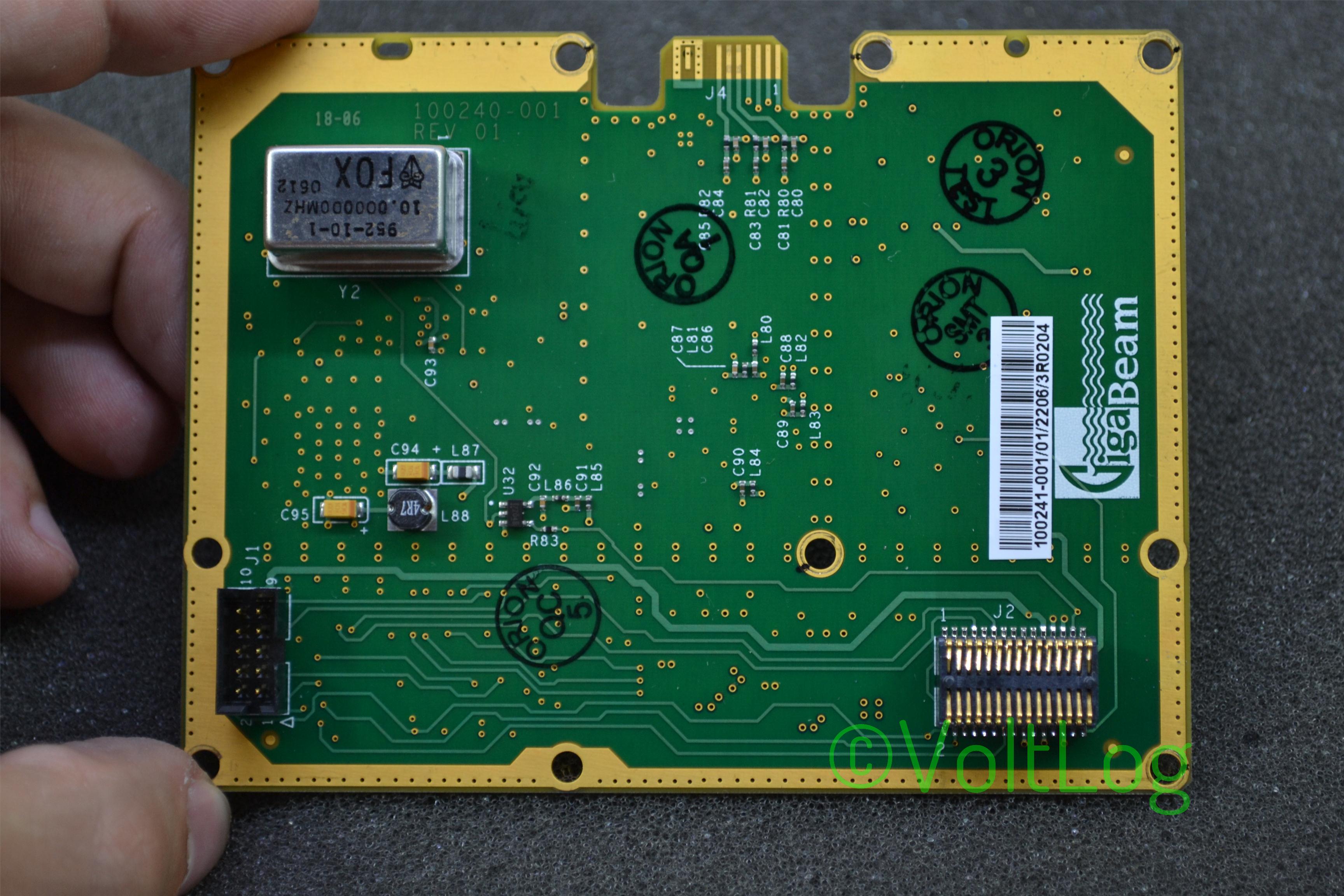
This antenna is called Gigabeam Wifiber and it’s manufactured by a company called Gigabeam Corporation that went bankrupt in 2010. The system is supposed to act like a transparent access point offering gigabit links over radio where fiber infrastructure is difficult to implement.
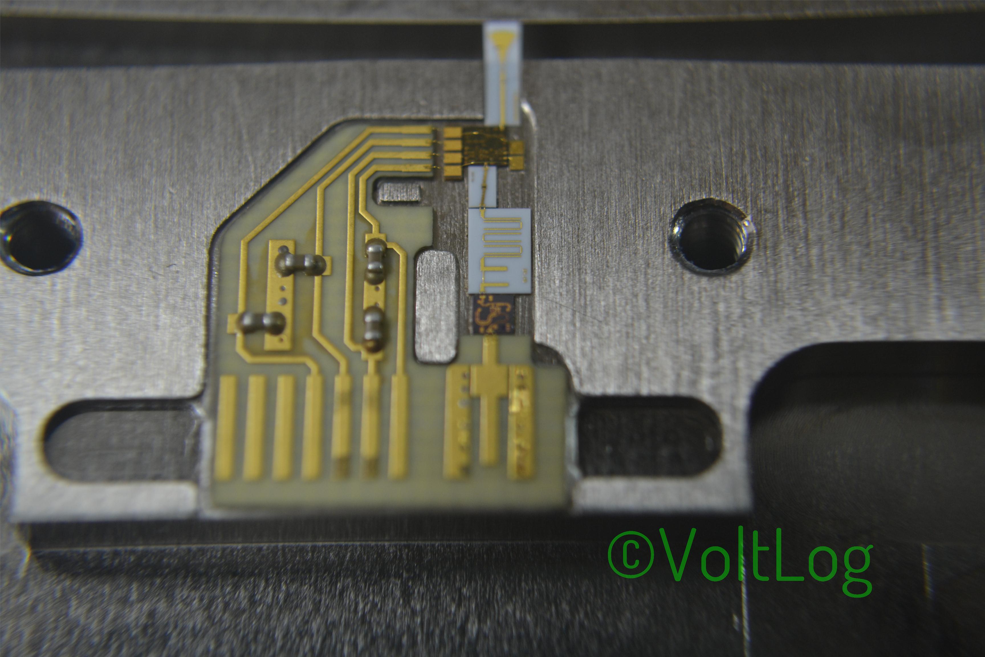
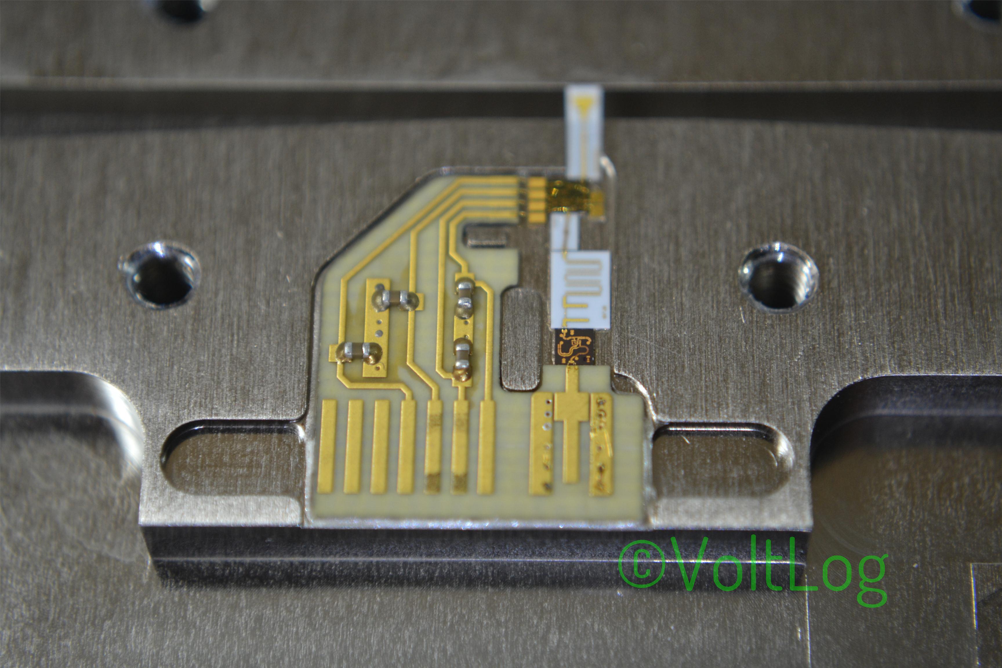
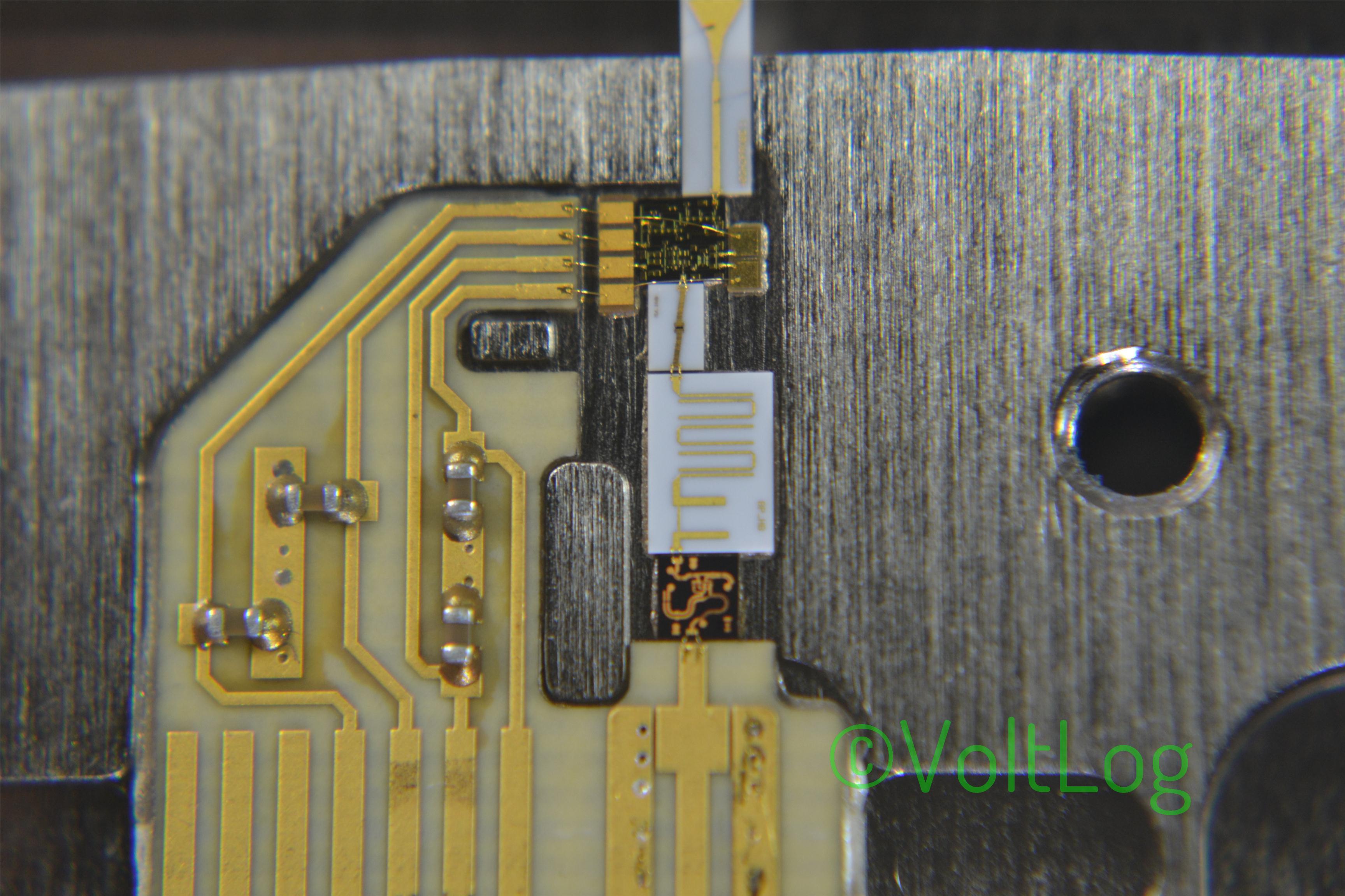
The radios operate in the 71-76 and 81-86 GHz radio spectrum bands and the modulation format is BiPhase Shift Key (BPSK). They have a transmit power of 20 dBm which translates to 100mW and that is not really a great deal of power but the antenna has a large gain of 50dB. The system takes a gigabit fiber input and on the other side from the receiving antenna you get a gigabit fiber output.
I have a pair of these, one of them is broken and I’m going to attempt to find the fault and maybe fix it. I’m hoping the problem is somewhere in the power section because that will be an easy fix because otherwise I don’t have a spectrum analyzer to take a look at the different RF stages.
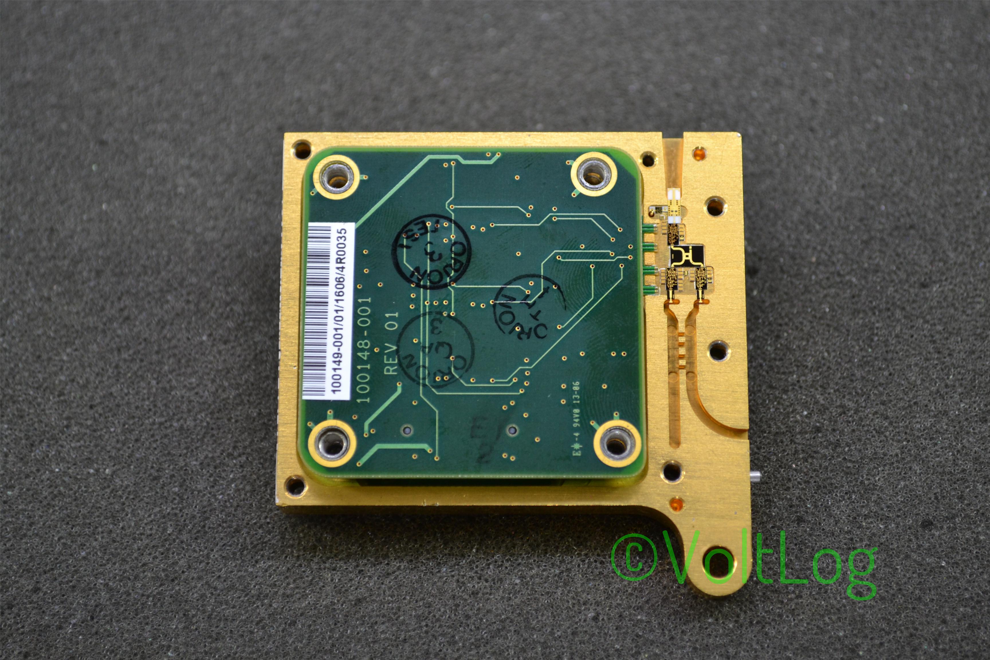
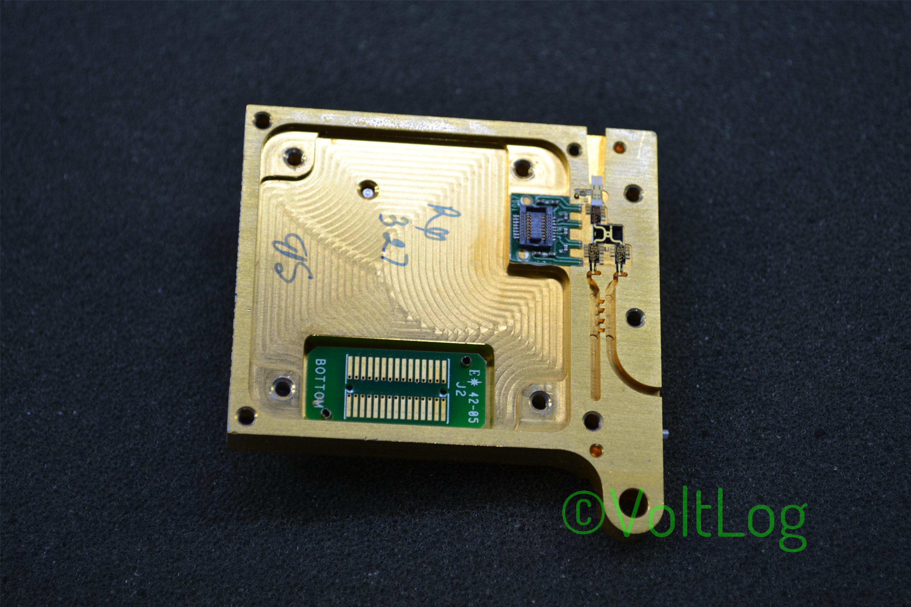
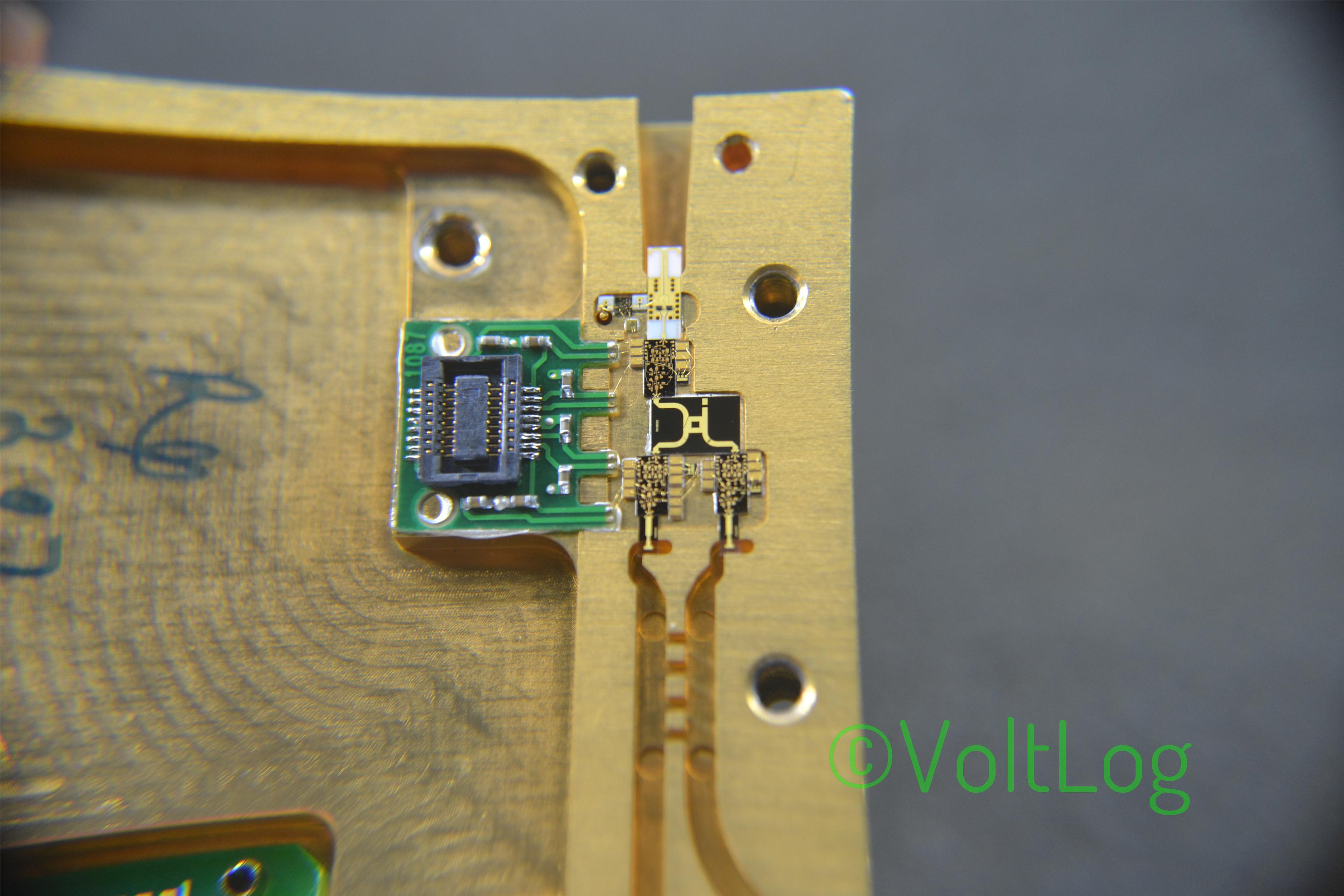
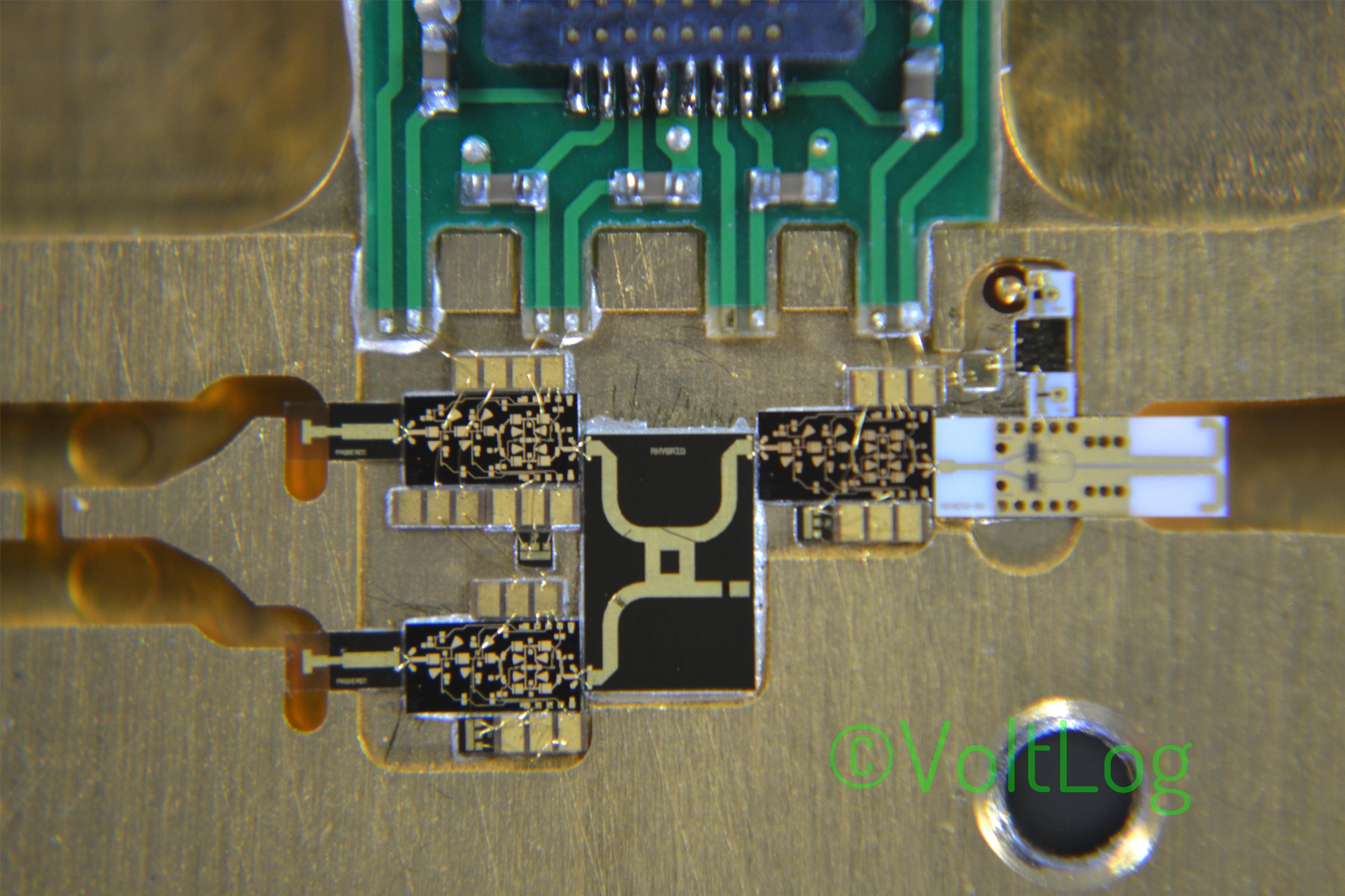
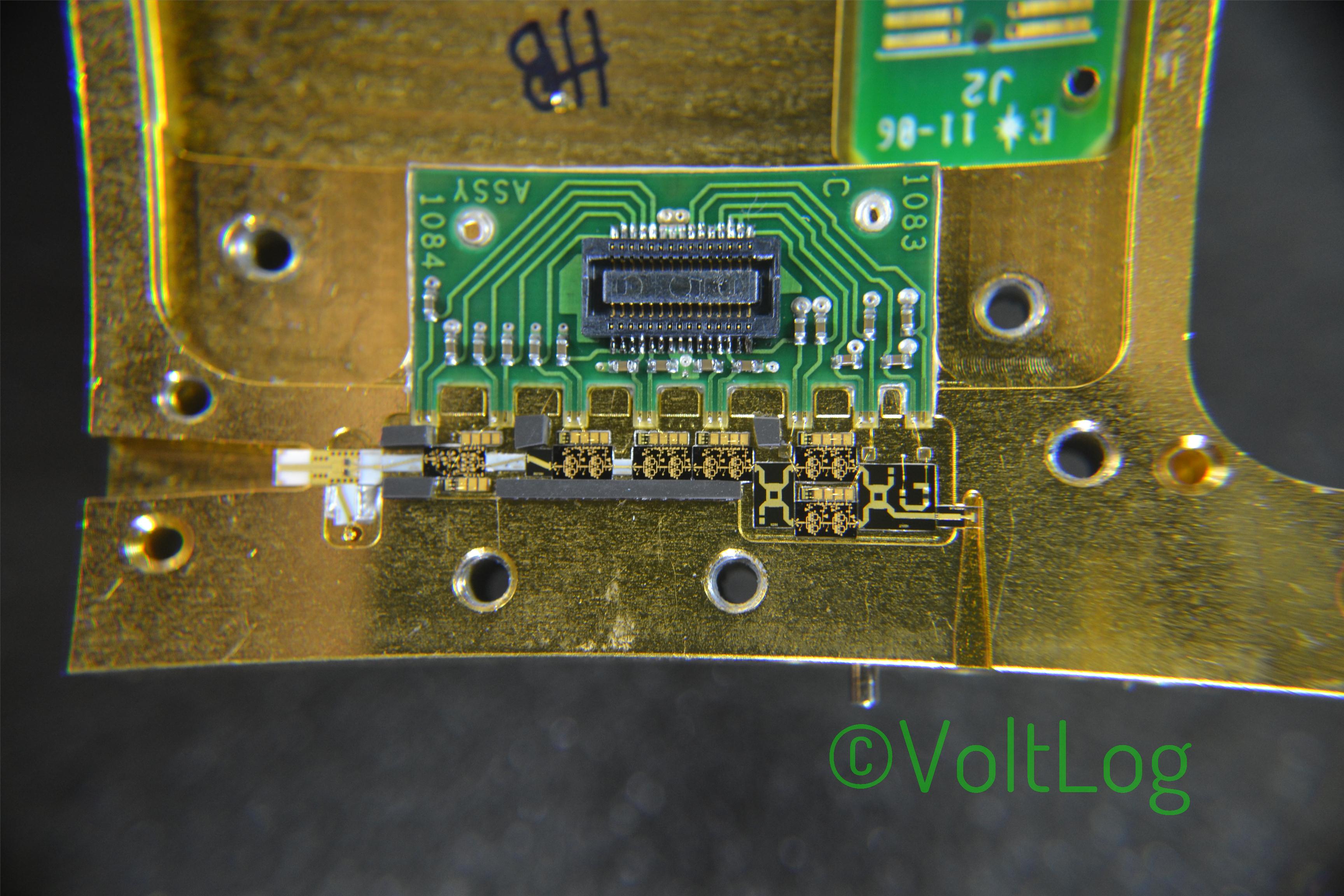
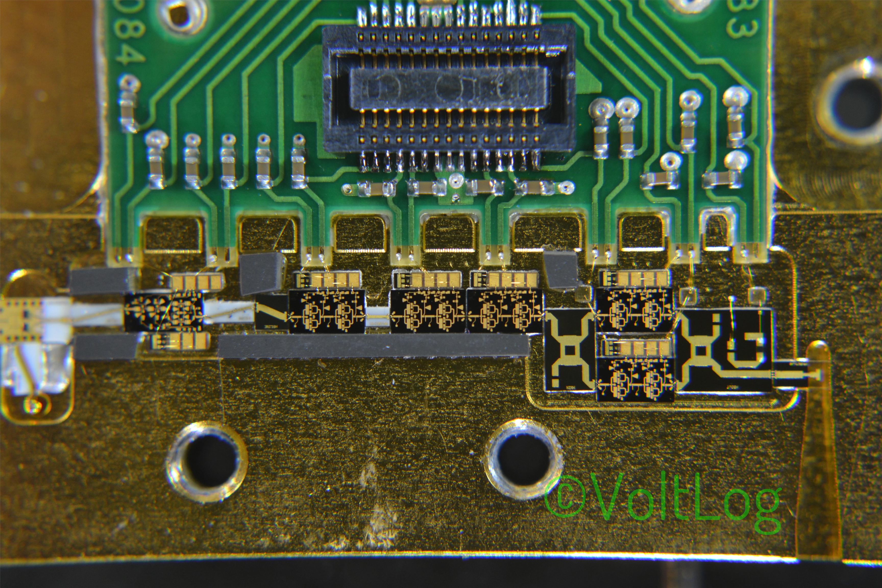
Anyway In this video you are only going to see the teardown but that should interesting on its own because I expect to see lots of RF magic inside and interesting system design.
Also checkout the high res photos below:
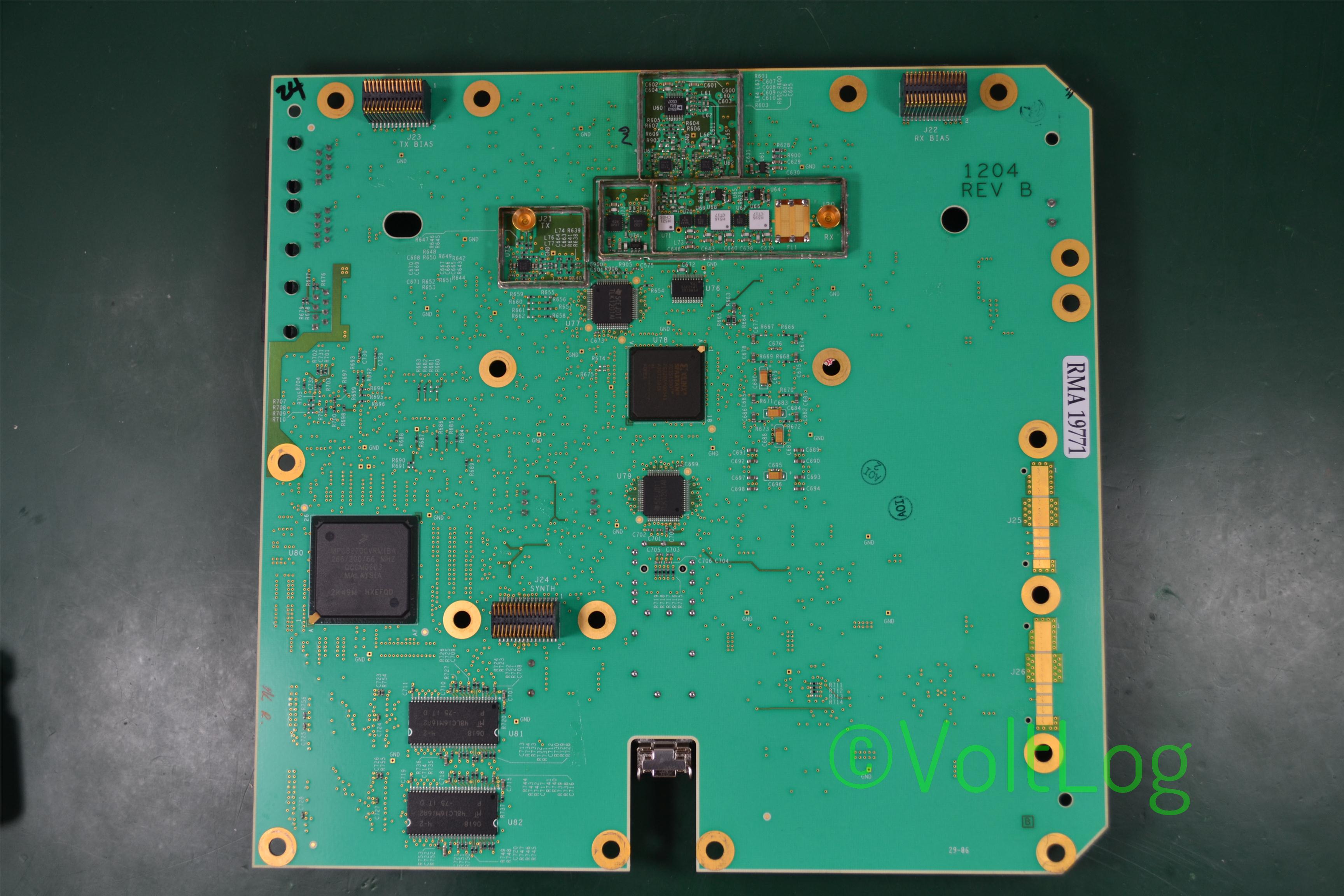
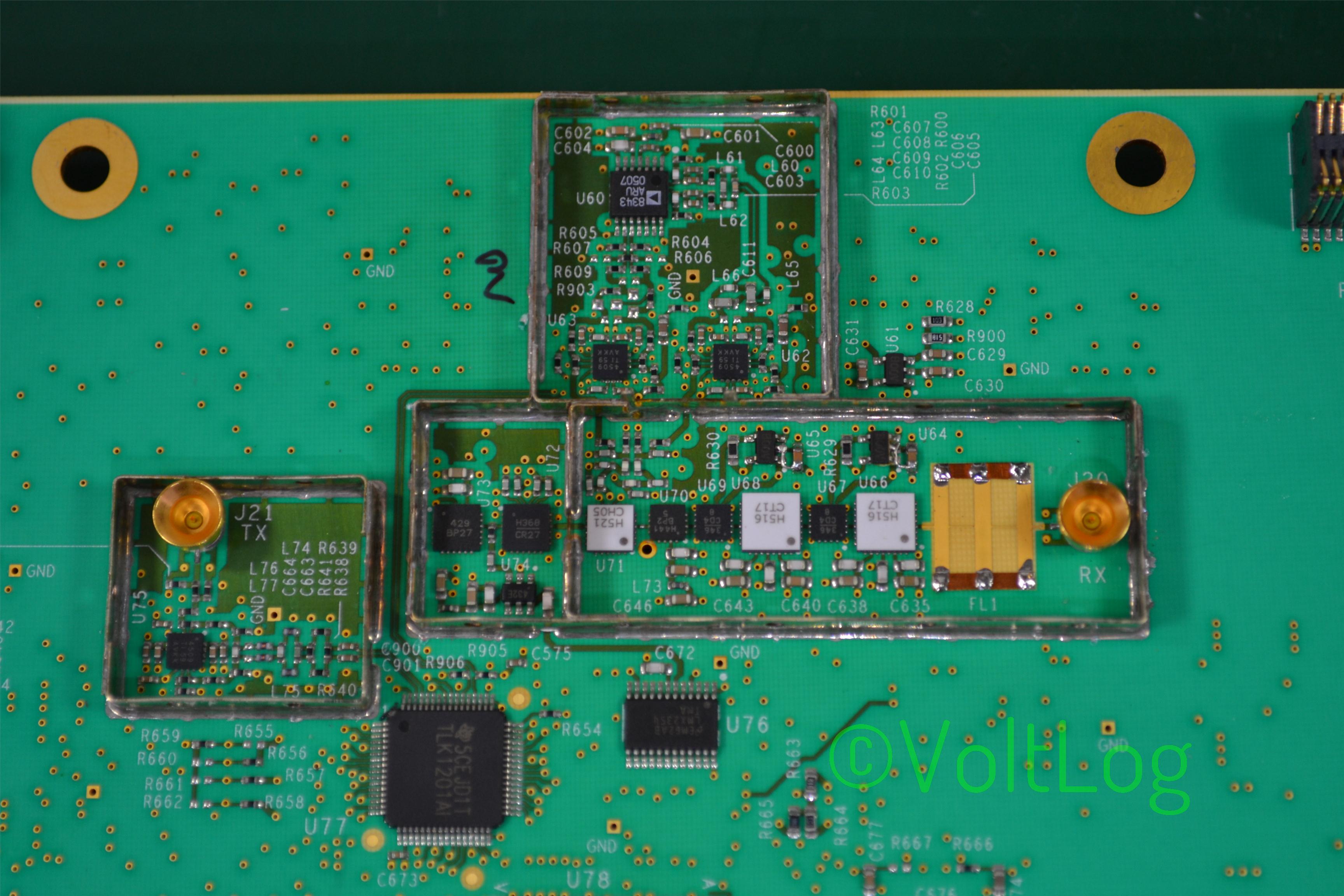
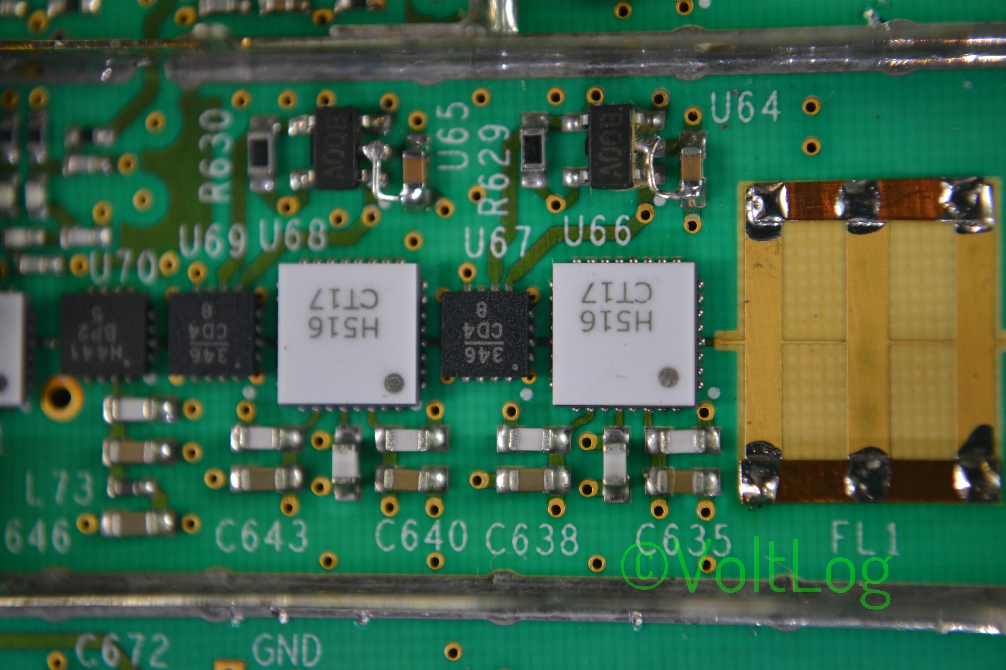
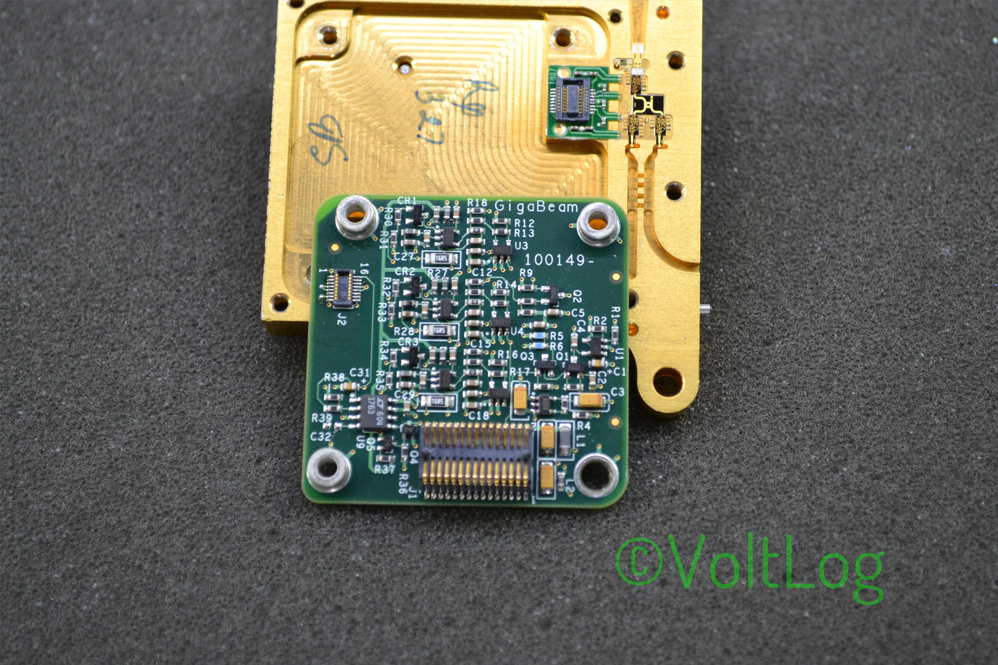
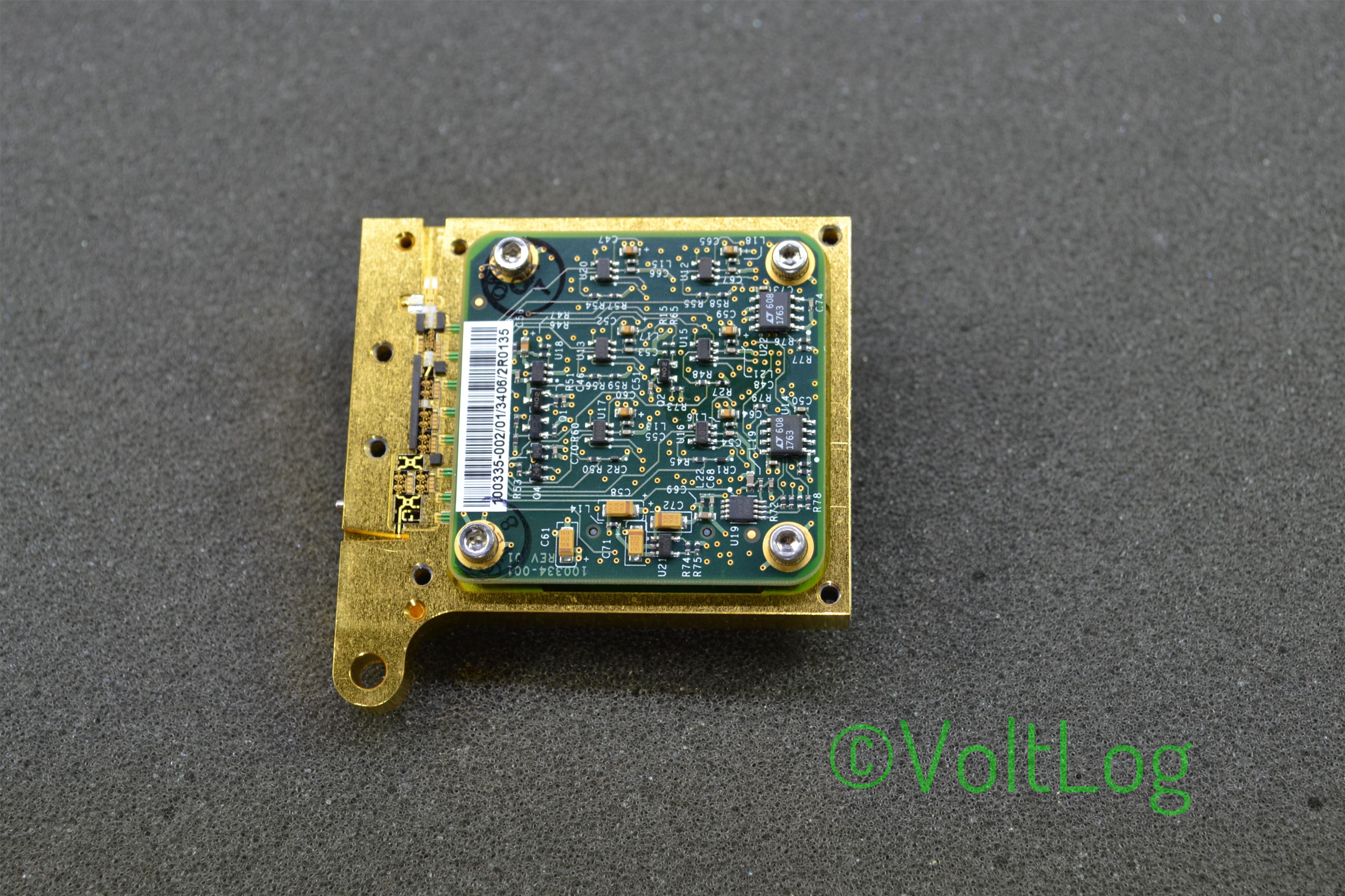
Here is a list of the components I managed to identify inside the unit:
- SMT4004: integrated programmable voltage manager IC which can monitor and control up to 4 independent supplies.
- Texas Instruments OPA725: low noise, high speed, rail-to-rail op-amp.
- Analog Devices AD8604: quad rail-to-rail, input and output, single-supply amplifier.
- Maxim MAX4663: quad, SPST, CMOS analog switch.
- IDT ICS601: Low phase noise 1 to 5 clock multiplier.
- XCF04: Xilinx In-System Programmable 4 Mbit ROMs for Configuration of FPGAs.
- Sipex 3232 RS232 transceiver.
- Semtech LC03-3.3: transient voltage suppressor.
- Intel XT971ALE: Single-Chip 10/100Mbps Ethernet PHY Transceiver.
- Pericom PI49FCT3803: 1 to 7 clock buffer targeted at networking applications.
- Maxim DS1339C: Real Time Clock.
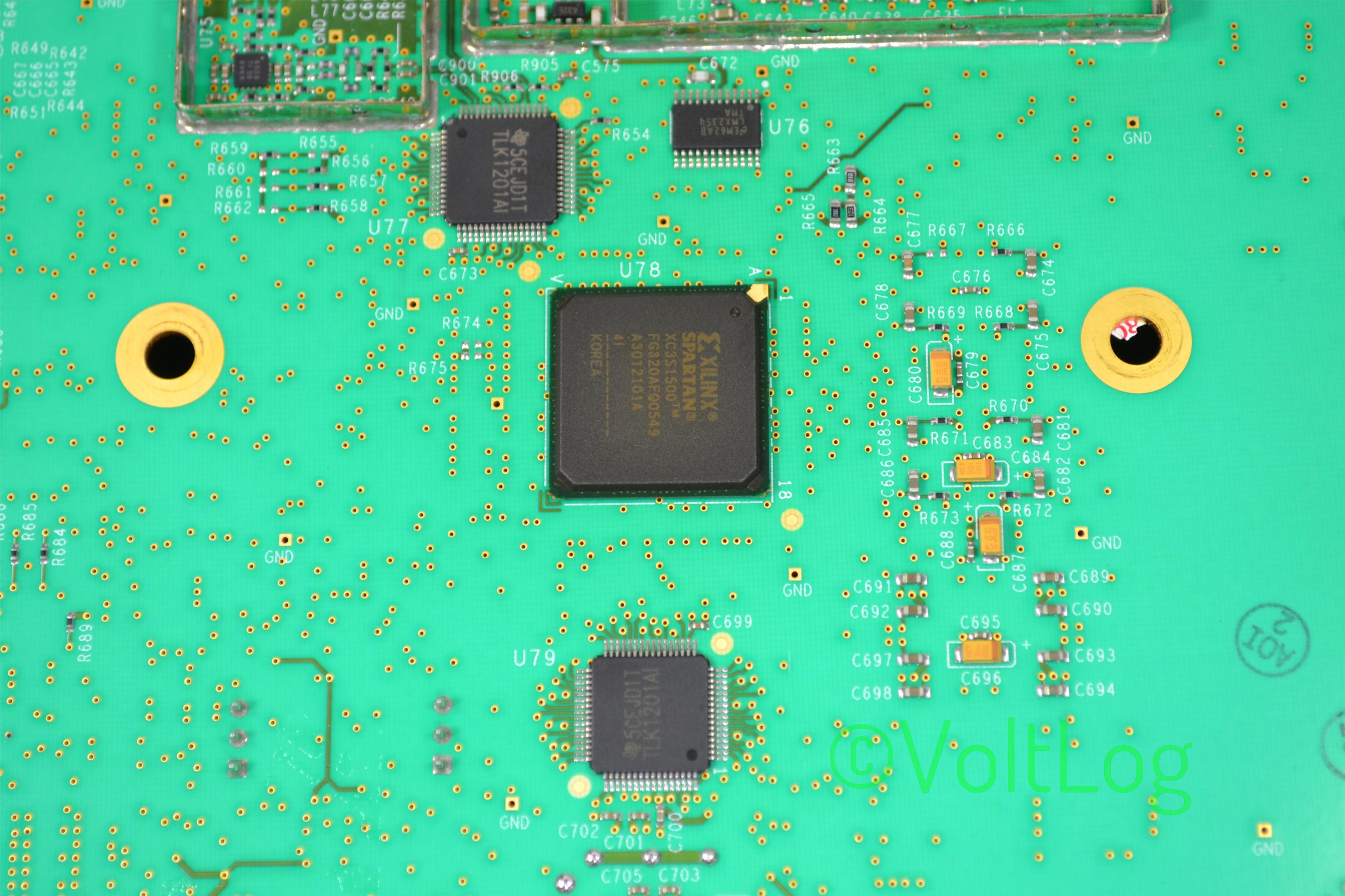
- TLK1201: gigabit ethernet transceivers.
- Xilinx XC3S1500: Spartan 3 FPGA with aproximately 30K logic cells inside.
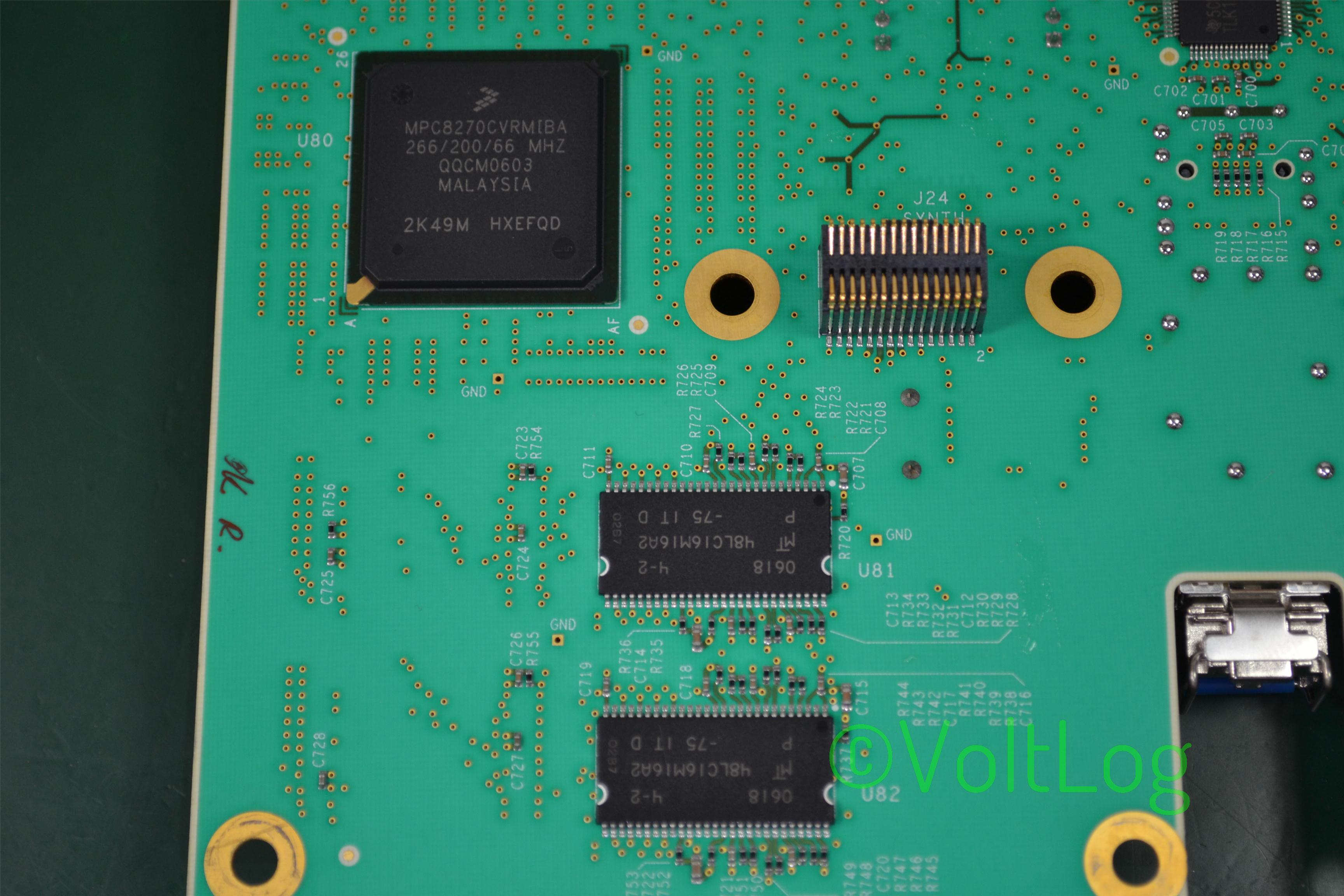
- MPC8270: PowerQUICC II Processor with embedded communications processor module targeted for telecom applications.
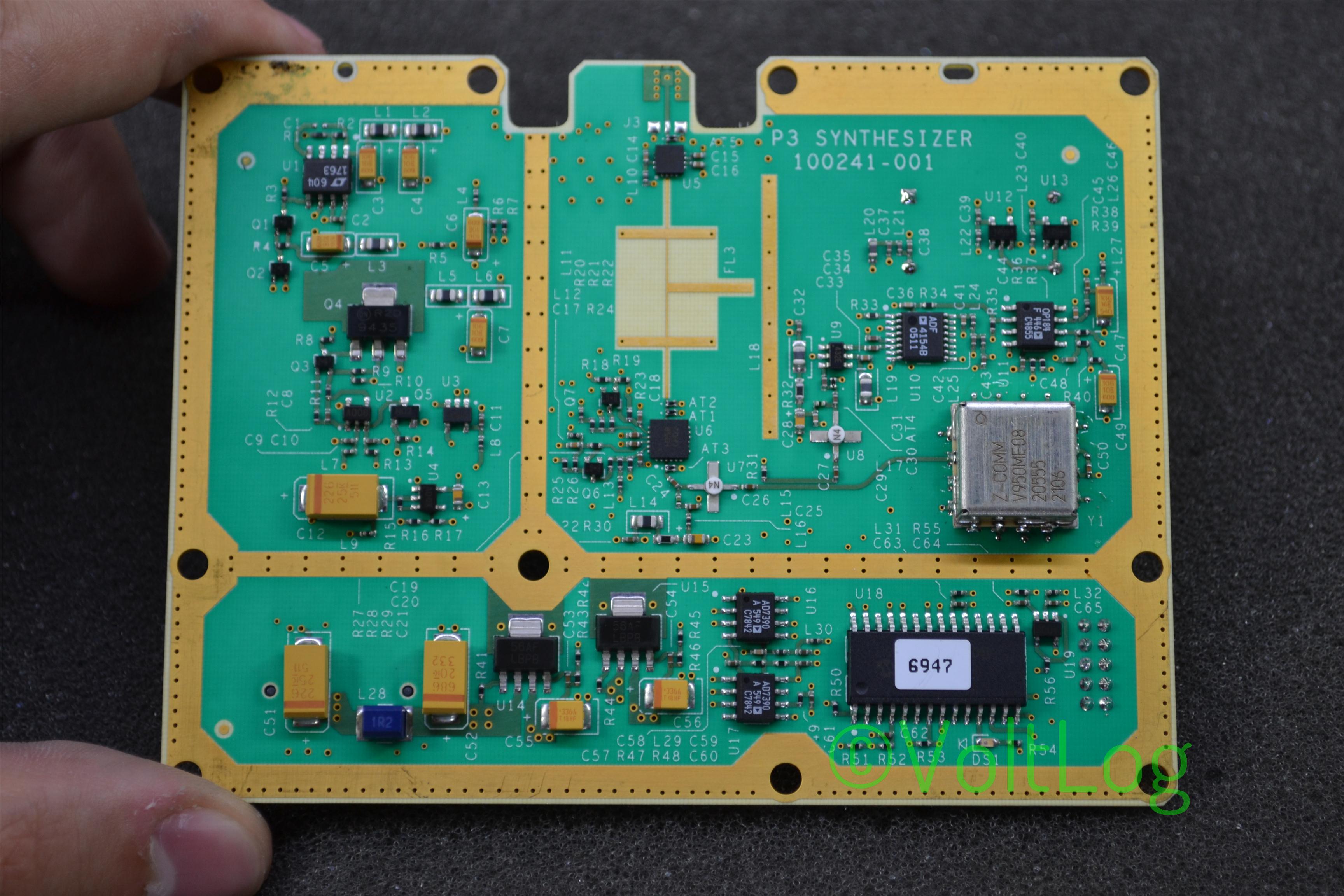
- Analog Devices ADF4154: frequency synthesizer.
- Hittite HMC368LP4: frequency doubler with both an input and output amplifier.
- Hittite HMC441: GaAs PHEMT MMIC medium power amplifier.