In the world of electronics testing and troubleshooting, having the right tools can make all the difference. Micsig, a renowned manufacturer of test gear, has recently released the CP503 current probe, and it’s a game-changer for professionals and hobbyists alike. The CP503 is a high-bandwidth current probe that can measure up to 50MHz (or 100MHz for the CP1003 variant), making it an ideal choice for analyzing current waveforms in various applications, including power supply design, automotive electronics, and more.
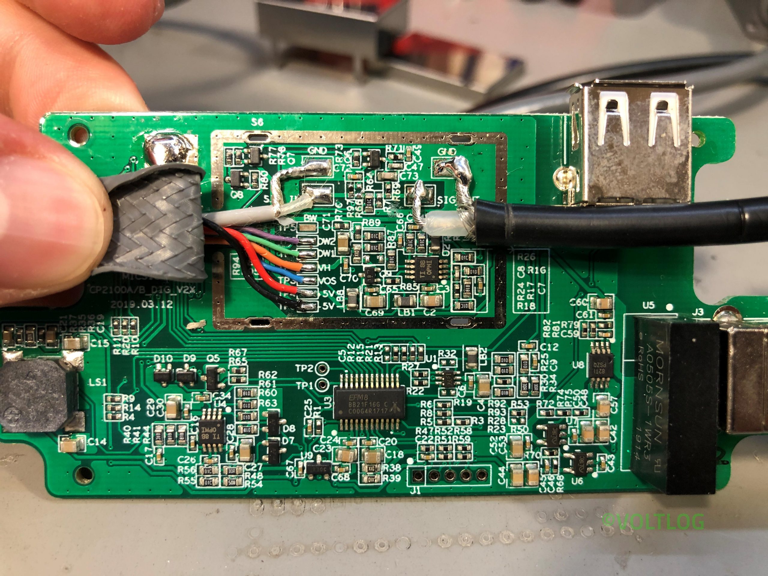
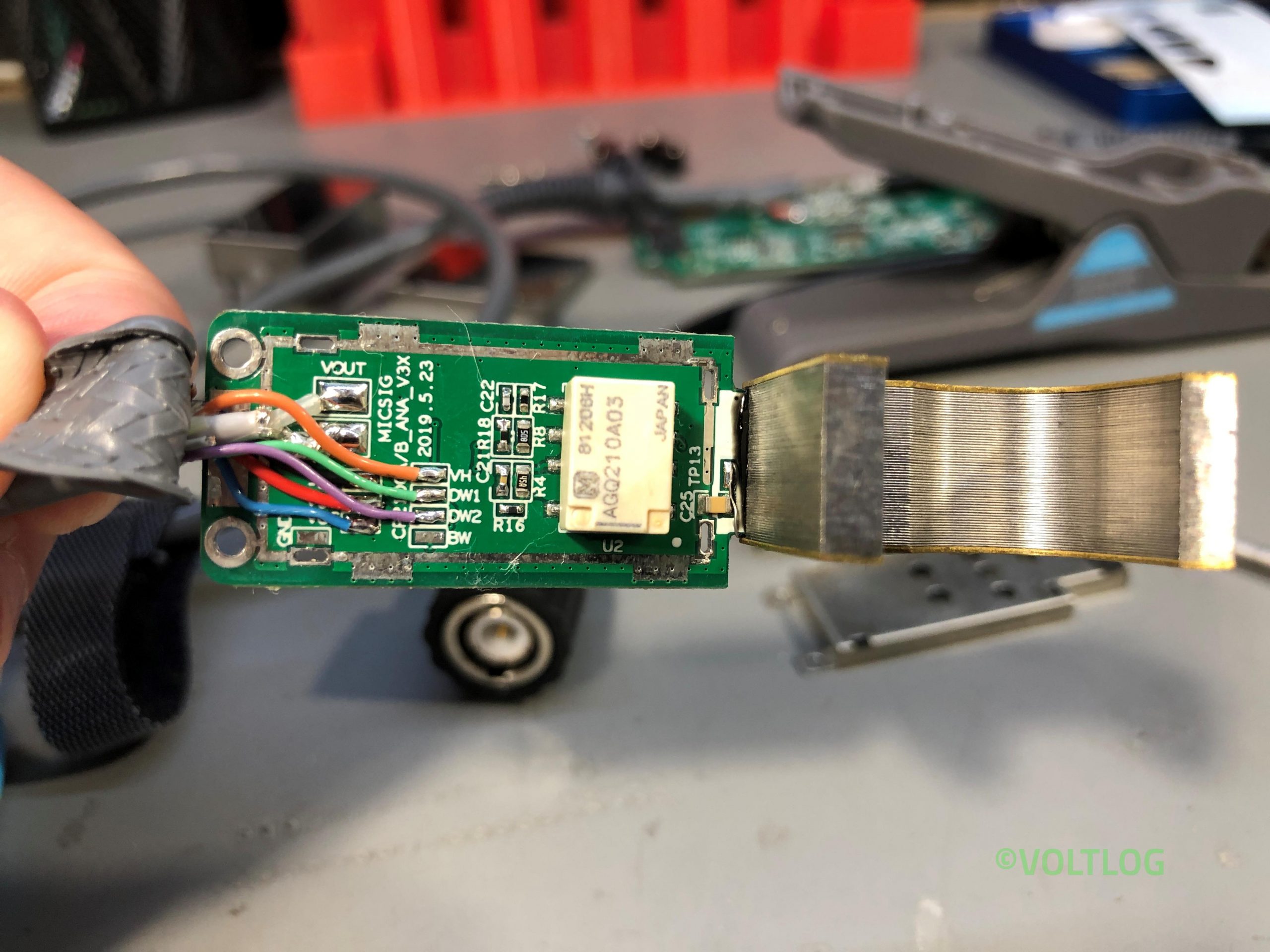
With its impressive bandwidth, the CP503 can capture even the most dynamic current waveforms with precision, allowing engineers and technicians to identify issues that might otherwise go unnoticed. One of the standout features of the CP503 is its UPI (Universal Probe Interface) connectivity option. This interface allows the probe to communicate directly with compatible oscilloscopes, enabling automatic calibration, parameter adjustment, and data transfer.
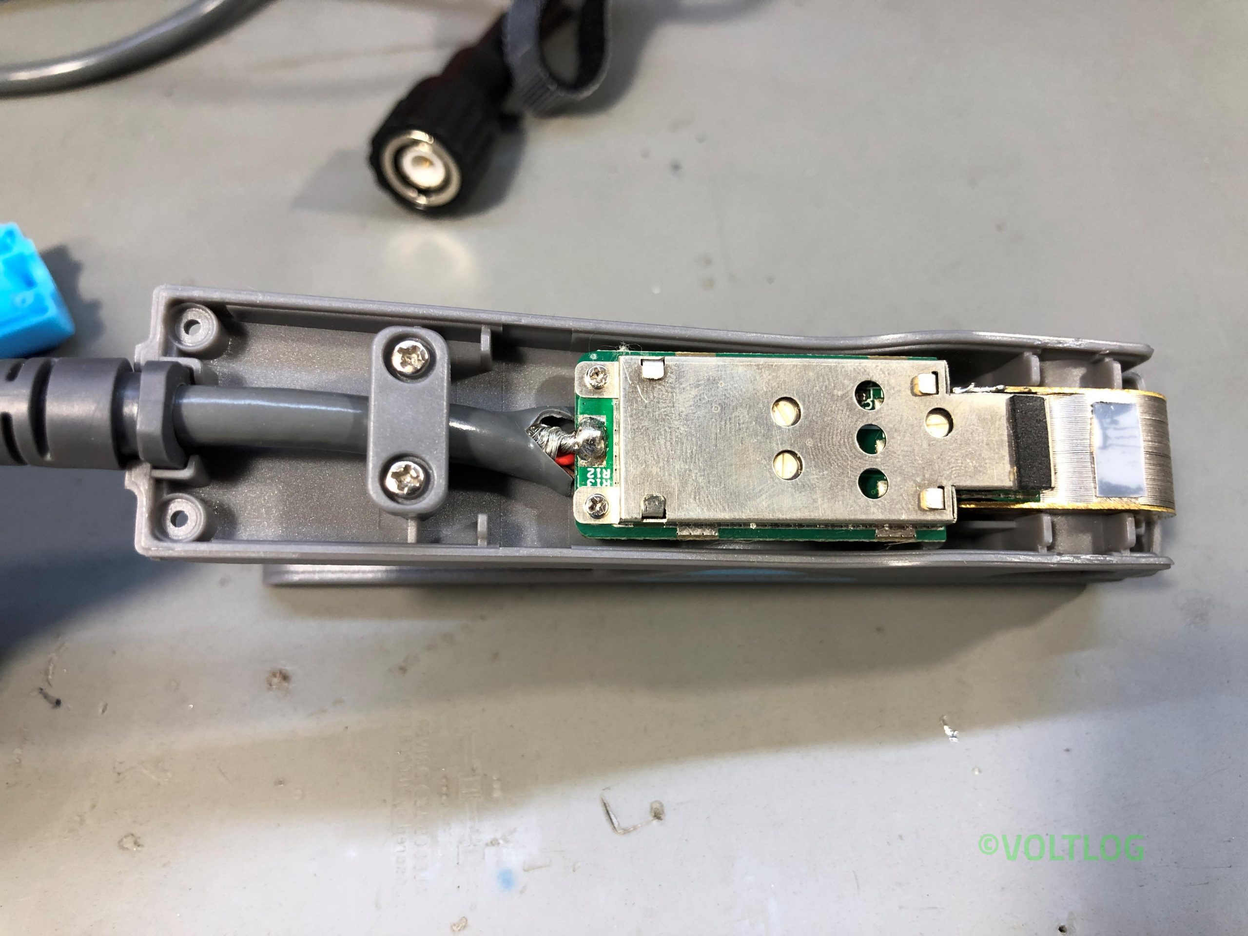
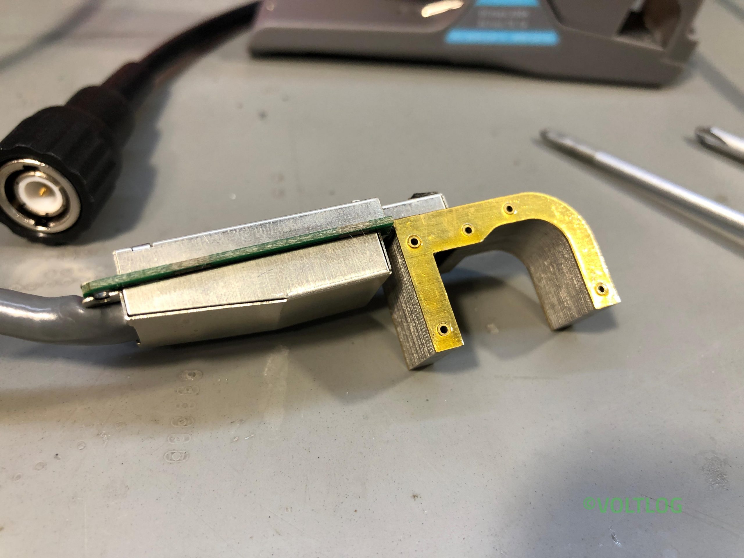
The result is a seamless user experience and increased accuracy, making the CP503 a true premium product. But the CP503 isn’t just about performance; it’s also built with quality in mind. The probe boasts a sleek and compact design, making it easy to maneuver in tight spaces. The cable feels soft and flexible, and the overall build quality exudes a sense of durability and reliability.
In terms of specifications, the CP503 impresses with its ±1% DC accuracy, low noise levels, and the ability to measure currents as low as 20mA on the 6A range and 50mA on the 30A range. These features make the CP503 a versatile tool for a wide range of applications, from measuring inrush currents to analyzing power factor correction circuits.