The most important part of this lab is obviously the workbench and this is something that I designed myself, I guess I can call this the Voltlog Workbench Design, it’s 2m wide with 80cm deep. The working surface comes out at about 95 cm from the floor. It sits on these adjustable feet but I haven’t even leveled it so far. Thanks to my friends at Welectron.com my working surface is protected with these nice premium ESD Mats. They are 100% and phthalates free, no bad smell, Heat and solder resistant, Chemical resistant, two layer ESD bottom side is conductive, top side is dissipative and they have this nice anti-reflective surface finish which is very comfortable to work on. I went with gray because it works best as a background for video shooting but you can opt for Blue as well. I’ll put a link to these in the description below, I highly recommend Welectron for their services & customer care and I highly recommend these ESD mats they are top quality.
Category: Test equipment
Best BST-933B JBC Clone Soldering Station Review & Teardown | Voltlog #340
Soldering tools is a big subject as there is no electronics bench or hobby without a soldering iron hence why I have several videos on the subject and why I will continue to do such videos when new tools are presented. Everyone knows and probably wishes for a JCB or Metcal station since they are very well known in the industry, they are reliable and most importantly very capable soldering stations but their price tag keeps them out of reach for the average hobbyist.
That’s why clones of the big names appear on the market and they can be bought for half the price of the original one, sometimes even less. That’s why the KSGER T12 soldering stations are so popular and why I use them. They support the original Hakko tips and so they provide identical performance to a Hakko station as long as you install a good quality T12 tip.
Which brings us to the subject of this video, this is the Best 933B, which is a clone of the JBC CD-B series compact soldering station. This has been on the market for a while but I recently got a chance to review this station when banggood offered to send me one for free. I would appreciate it if you would check out the links I place in the description, this will ensure I can get more gear to review in the future. Price wise, if you were to order one of these it would cost you about half the price of the original JBC station. Depending on where you order the original one is around 400EUR while the Best station is about 200EUR on banggood.
Micsig CP2100A Best Affordable Current Probe | Voltlog #330
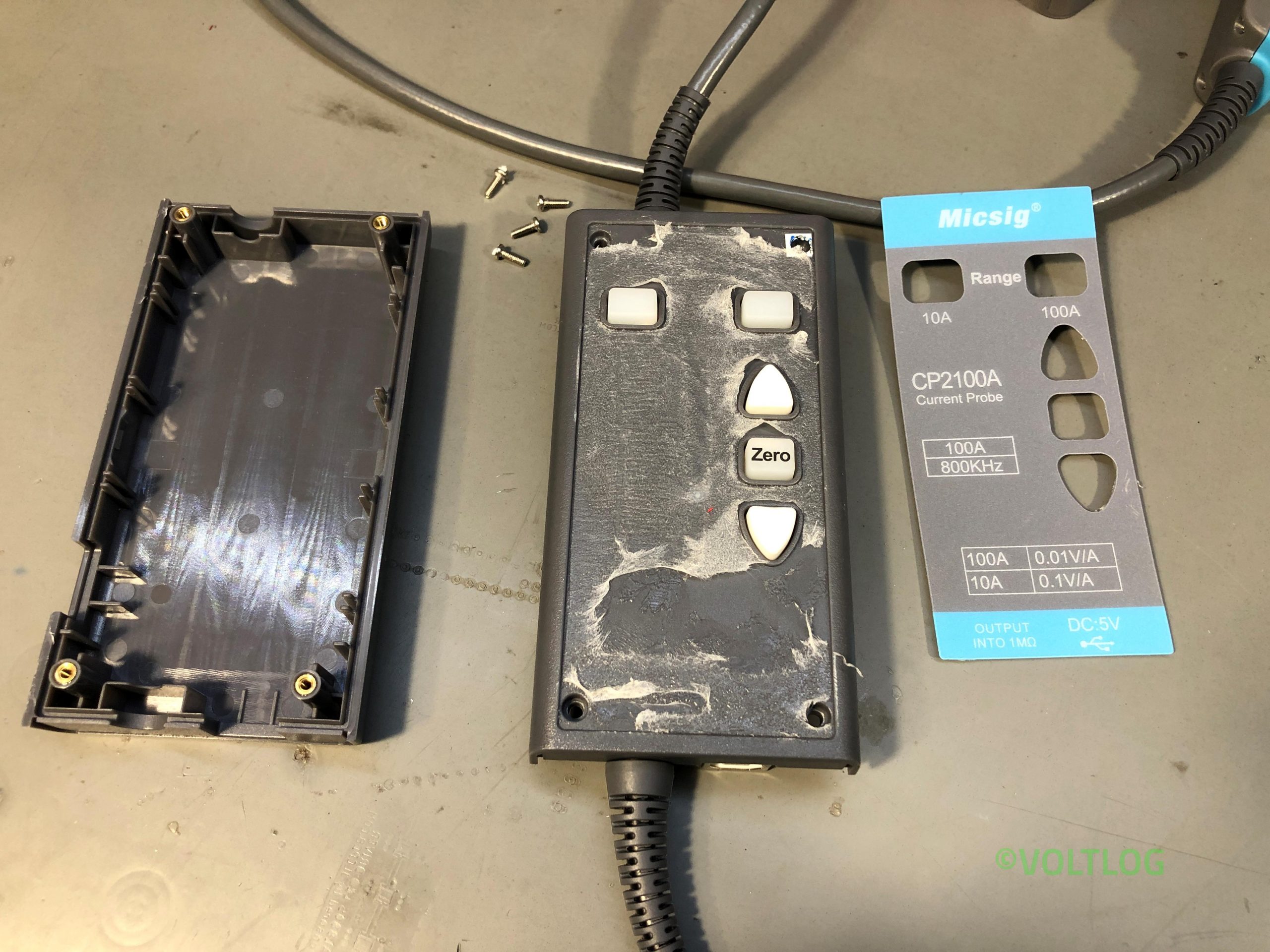
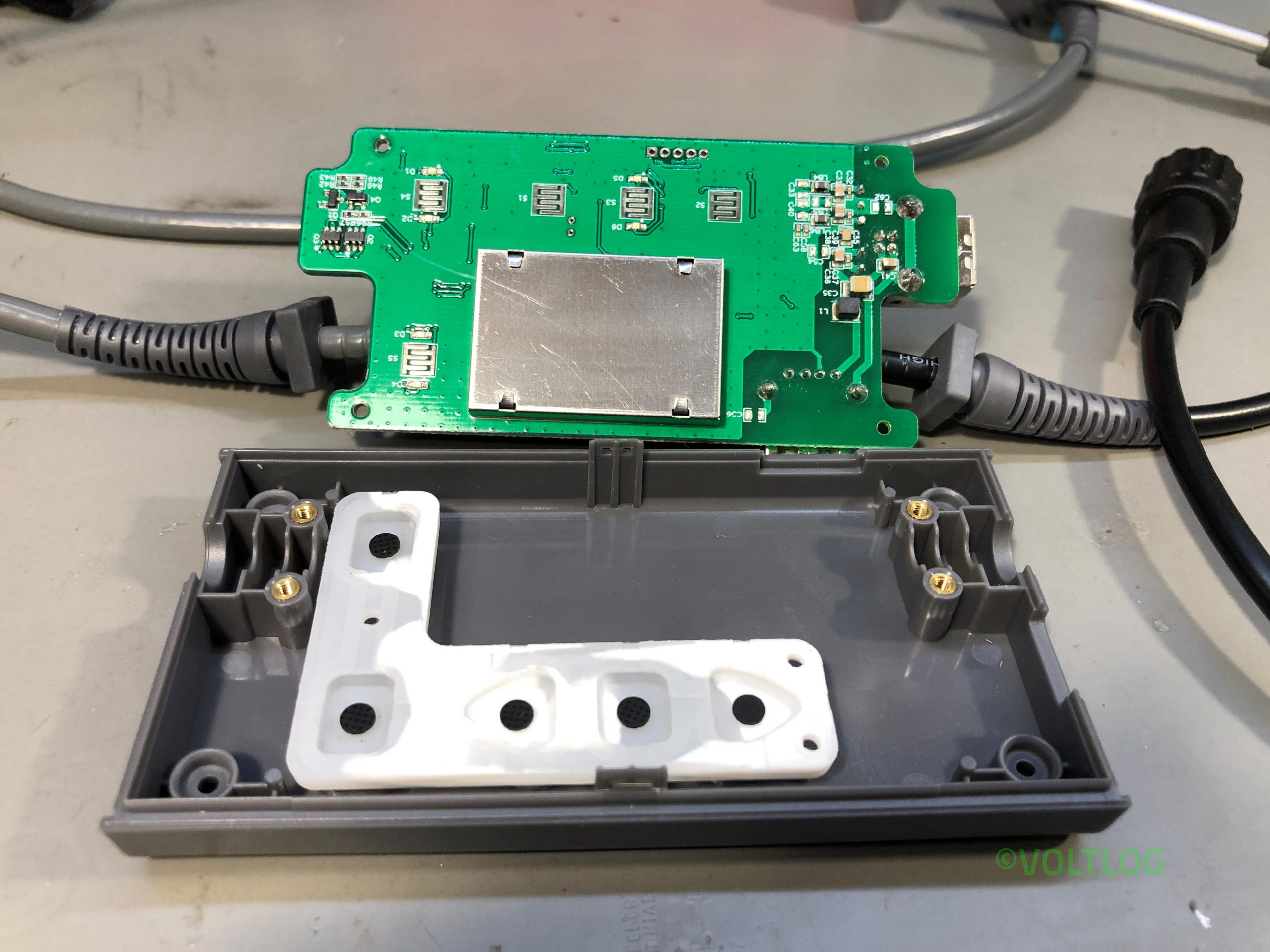
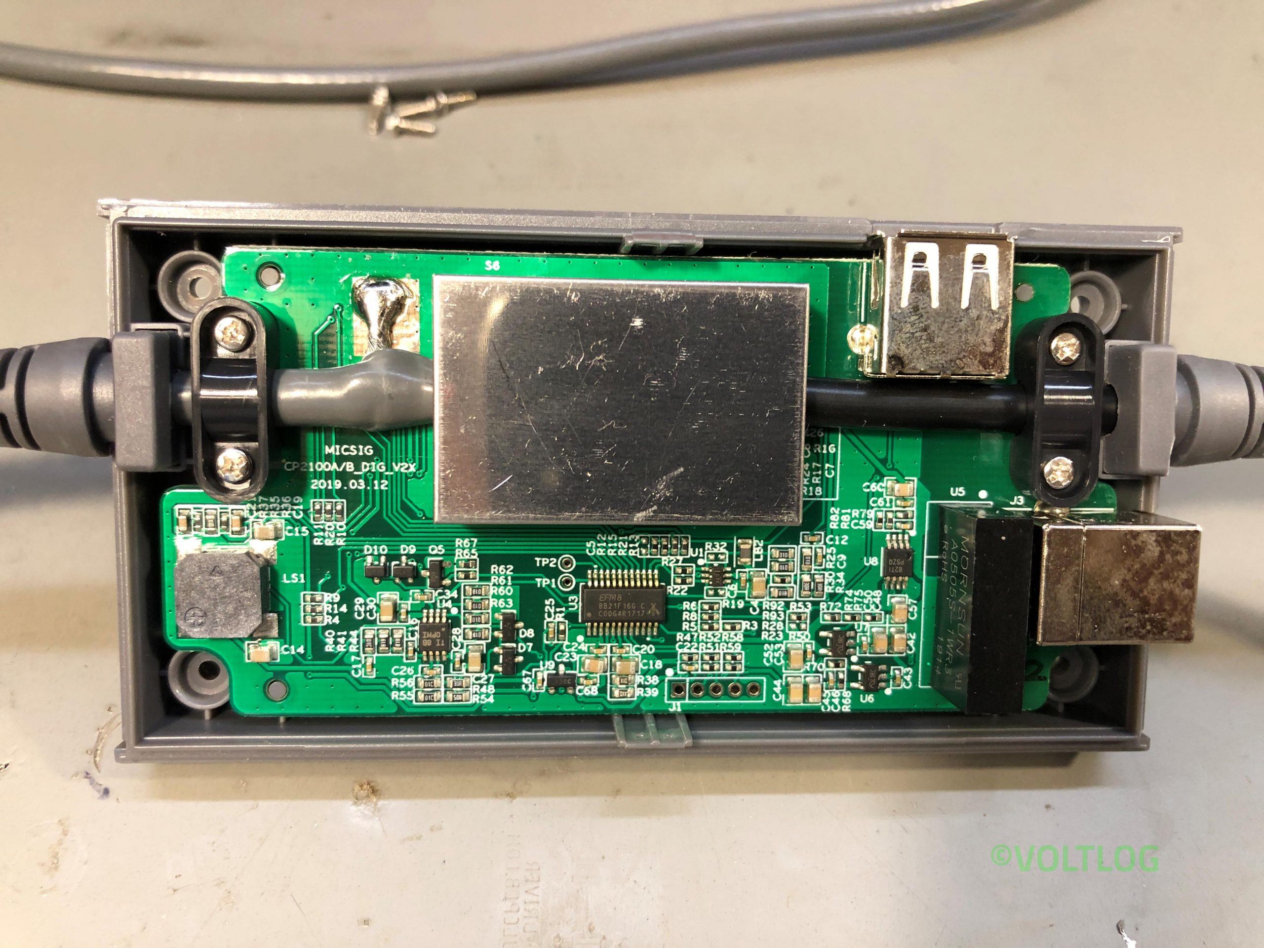
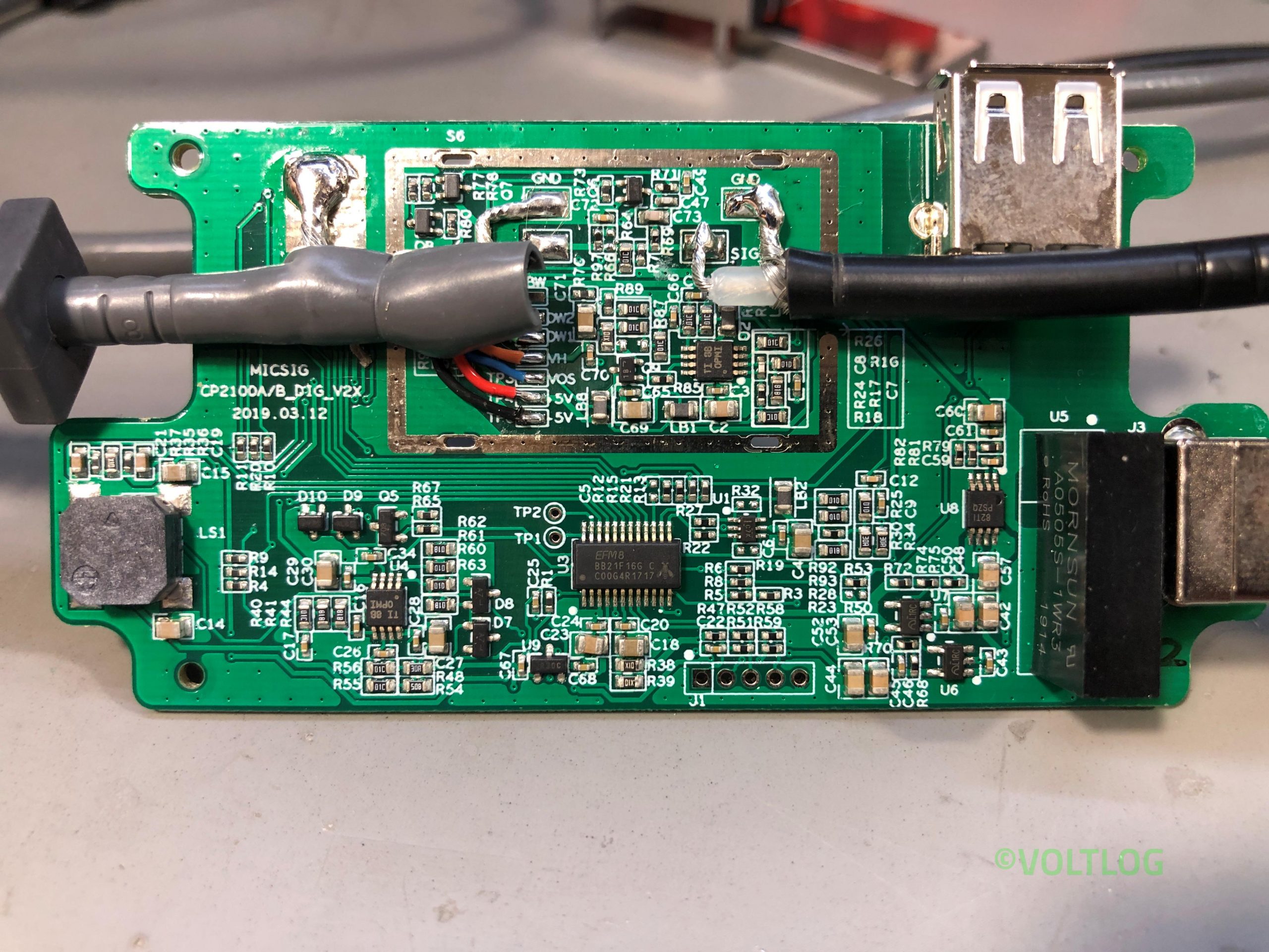
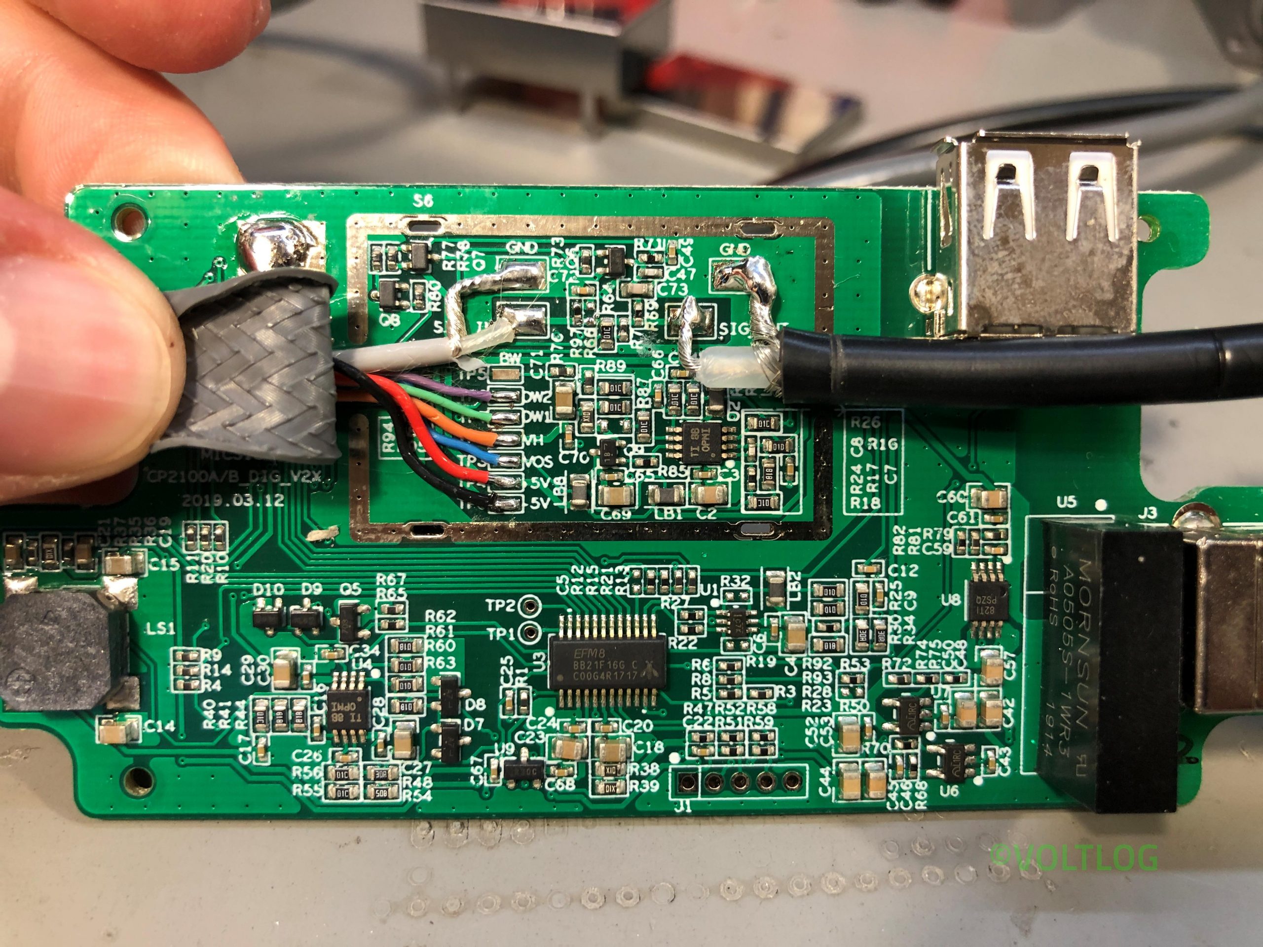
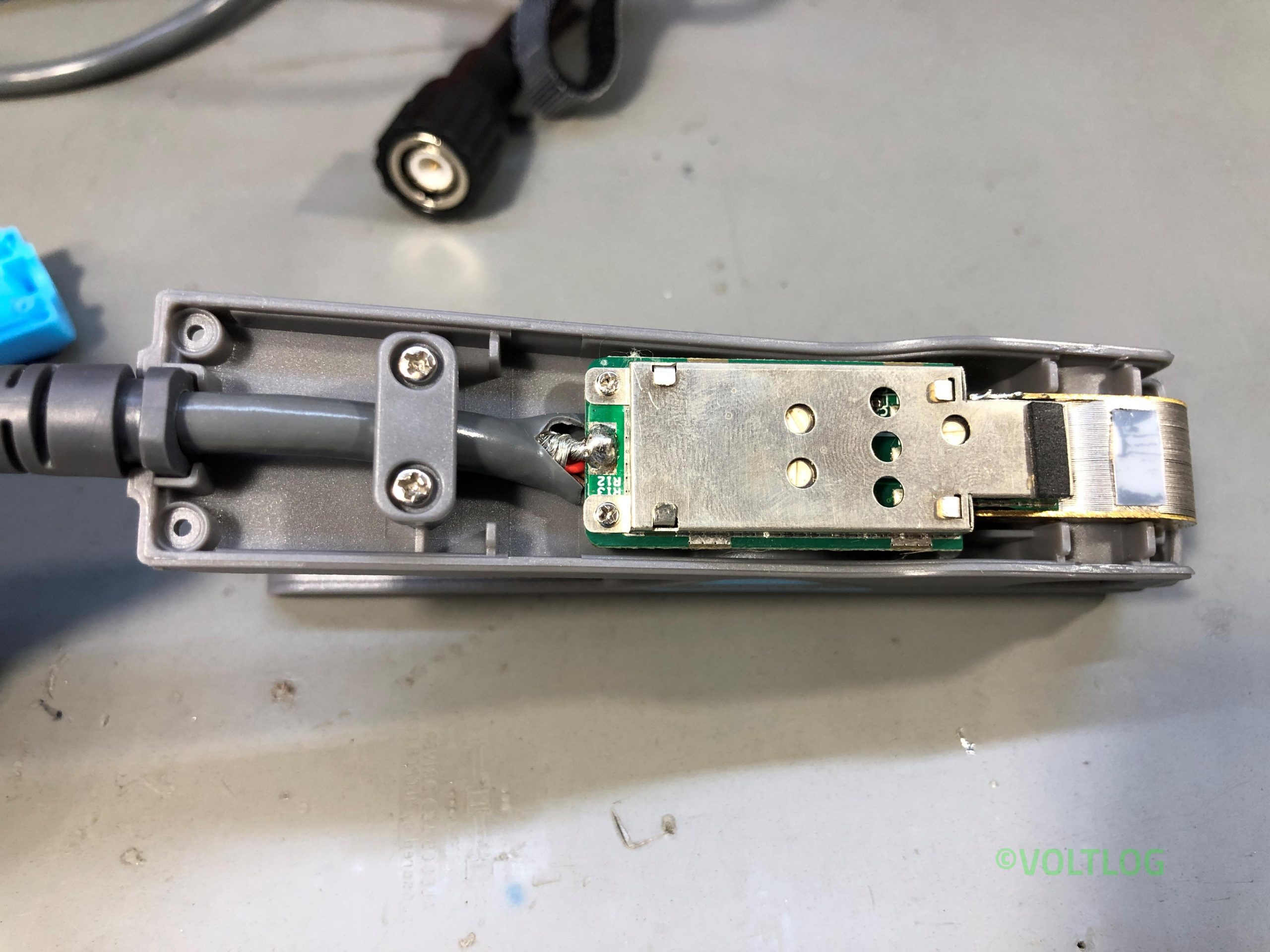
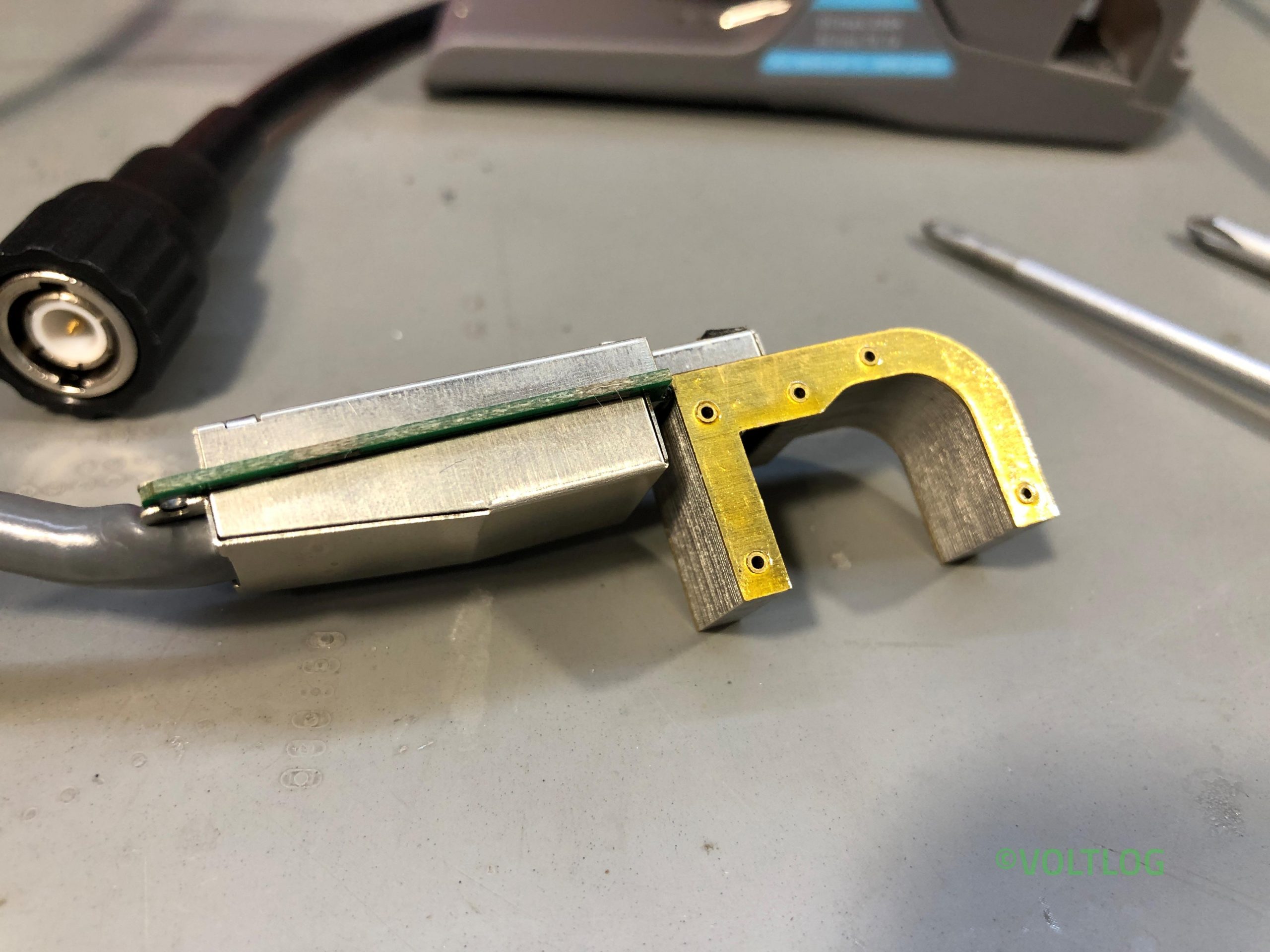
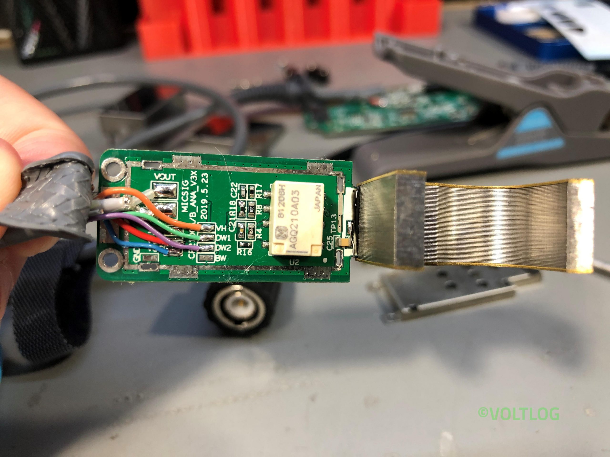
So this is the Micsig CP2100 series current probe, it’s my first piece of equipment from Micsig but I’ve been hearing good things about them so I kinda have high expectations for this product.
What I have here is the CP2100A variant which is rated for 800KHz bandwidth, there is also a B variant which is rated for up to 2MHz in the latest revision, that one is a bit more expensive and I would only recommend getting it if you really need that bandwidth, otherwise there shouldn’t be any other difference between the two models. I don’t know if I mentioned this already but obviously it can measure AC and DC, it has two ranges, 10A and 100A. There is a zero function on the module for automatic zero adjustment and you can also do manual offset adjustments with these arrow keys.
Micsig specs this as 3% ±50mA accuracy for the 10A range and 4% ±50mA for the 100A range but from what I’ve been reading on the forums, this is actually better than the spec, you can pretty much measure down to 50mA without having to worry about that ±50mA but we’ll put that to a test later. Included below you see a set of images from the teardown.
Fix Microscope Ring Light Reflections With These Projector Lamps | Voltlog #327
You’ve no doubt seen this before on the channel, it’s the trinocular microscope that I have reviewed in Voltlog #282 and I’ve also done a bunch of follow-up videos since then on how to improve the camera system. This comes equipped with an LED ring lamp to illuminate the working surface if you’ve used a setup like this for soldering you’ve no doubt experienced the reflections you get from shiny surface likes the PCB material, especially when you start adding flux into the mix. I’ll overlay some images so you can get a sense of what I’m talking about but basically, since the ring light is shining light right from where the barlow lens is, there are these annoying reflections.
Today I want to show you an alternative lighting system that will help go around that problem. This is a system with individual gooseneck LED lamps. Having this flexible gooseneck tube allows you to position the lamps at an angle that would avoid those nasty reflections.
Making Kelvin Test Leads For My LCR Meter | Voltlog #326
A common mistake when building kelvin 4 wire test leads is to use standard alligator clips because in a standard clip the top and bottom jaw are electrically connected at the hinge point. This kinda defeats the purpose of having separate sense lines if they are getting shorted at some point with the current carrying trace. For a true kelvin connection you would need a special type of alligator clip, like the ones shown in this video, these have a plastic hinge and the top and bottom jaws are not electrically connected. These can be quite expensive if they are made by a good manufacturer but I got mine from aliexpress for cheap, they do not excel in quality but good enough for the type of instruments I am going to be using them with and with the amount of work volume they are going to see on my bench they will last a while.
Gopher NPS1601 Open Source Control Panel | Voltlog #322
A while ago I decided to start this project of re-designing the front panel for this power supply to give it more functionality, make it an awesome power supply cause as it is, it’s a good power supply but I think we can make it an awesome power supply. I made an announcement on the channel a while ago so several people joined the project, this is a team effort and right now it’s time to show you the first hardware prototypes and to discuss the choices we’ve made in terms of hardware.
ScopeShunt Visualising The Current Waveform With Your Oscilloscope | Voltlog #310
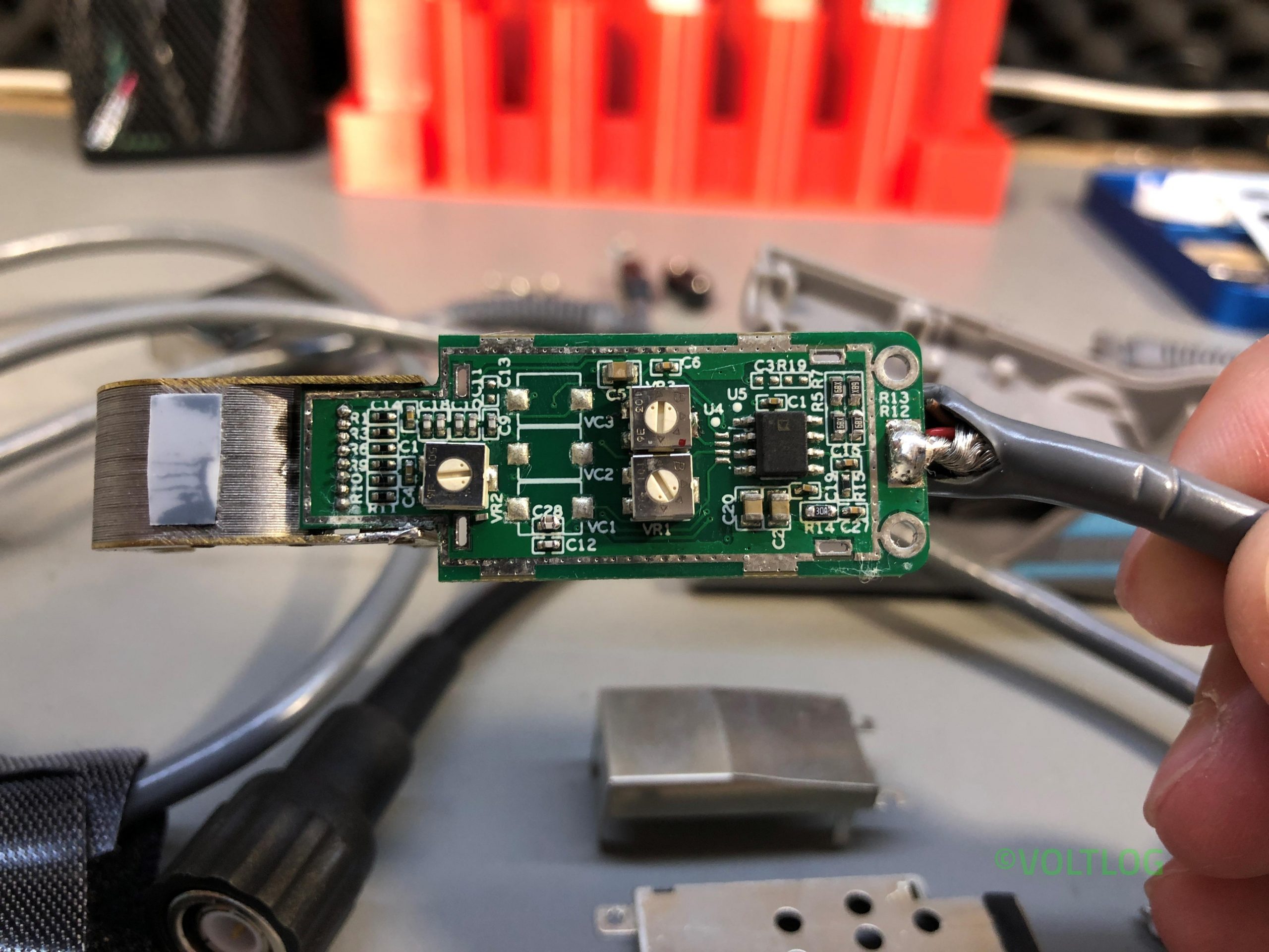
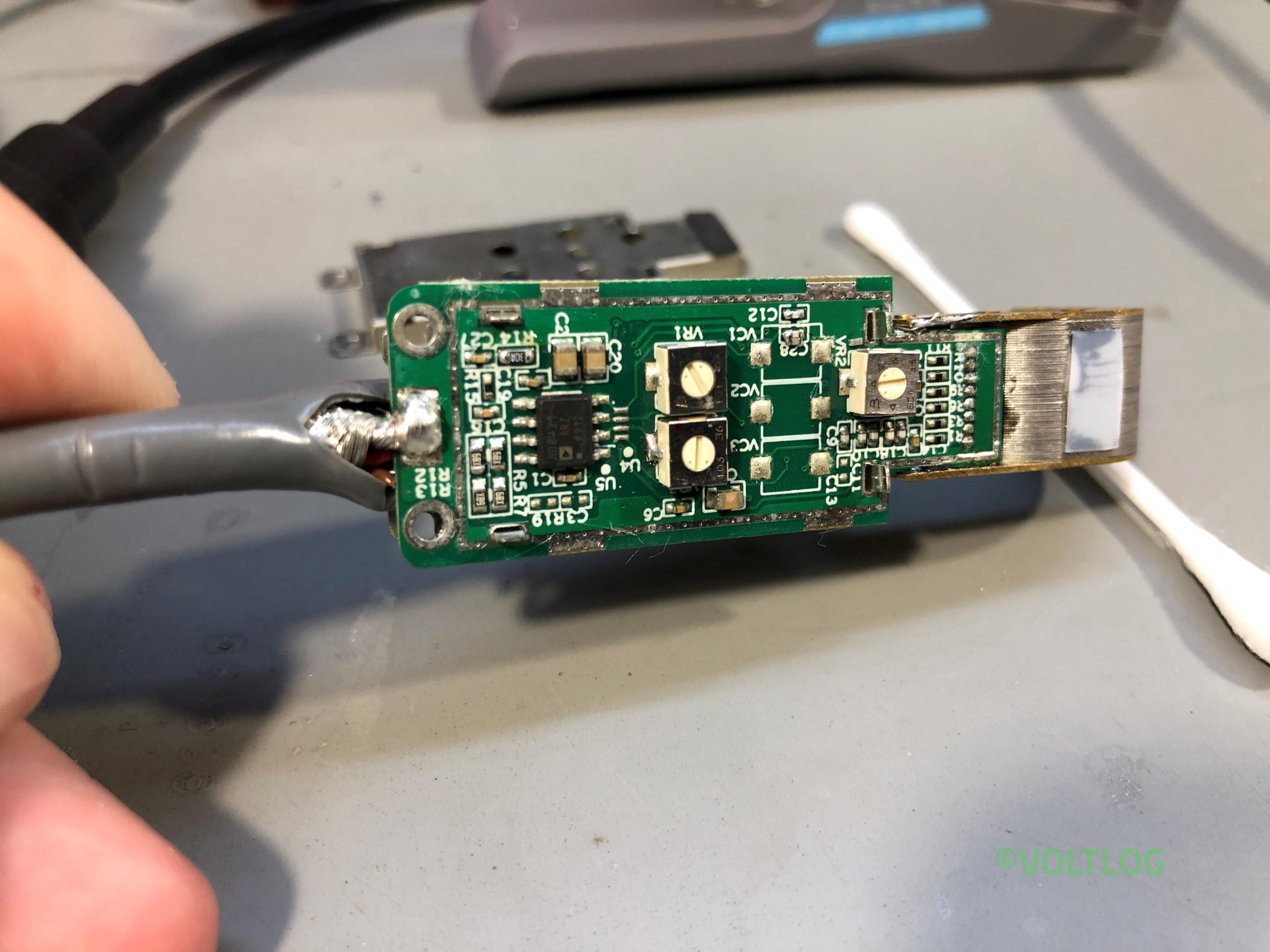
We usually use an oscilloscope for visualizing a voltage over time but sometimes it’s also useful to visualize the current waveform over time. The right way to do it is to get a current probe which can sense the current and convert that to a voltage that the oscilloscope can display however such devices are pretty expensive, they can be around $1000 even for an entry level one like the Rigol RP1001C which is only rated up to 300KHz bandwidth.
But we can improvise something for a much lower cost and it should allow us to visualize the current waveform on the oscilloscope. You’ve probably seen me use a shunt resistor when testing power supply to take a look at the current waveform. Because as you know passing a current through a resistor will generate a voltage drop.
That voltage drop is directly proportional with the passing current and with a round value resistor we can have an easy to use transformation ratio between voltage and current. All we have to do is o introduce this resistor inline between our power supply and the device under test
For example if I have a 1ohm resistor, we have a 1:1 ration, for each mA passed through that resistor we will have 1mV of voltage drop that our oscilloscope can display. Such a circuit will of course have it’s limitations, for example it won’t work very well when testing low voltage low power devices because our resistor will introduce a burden voltage, which will drop our supply voltage to the device under test. This is also not an isolated measurement so it might not be safe when connected with higher voltage circuits.
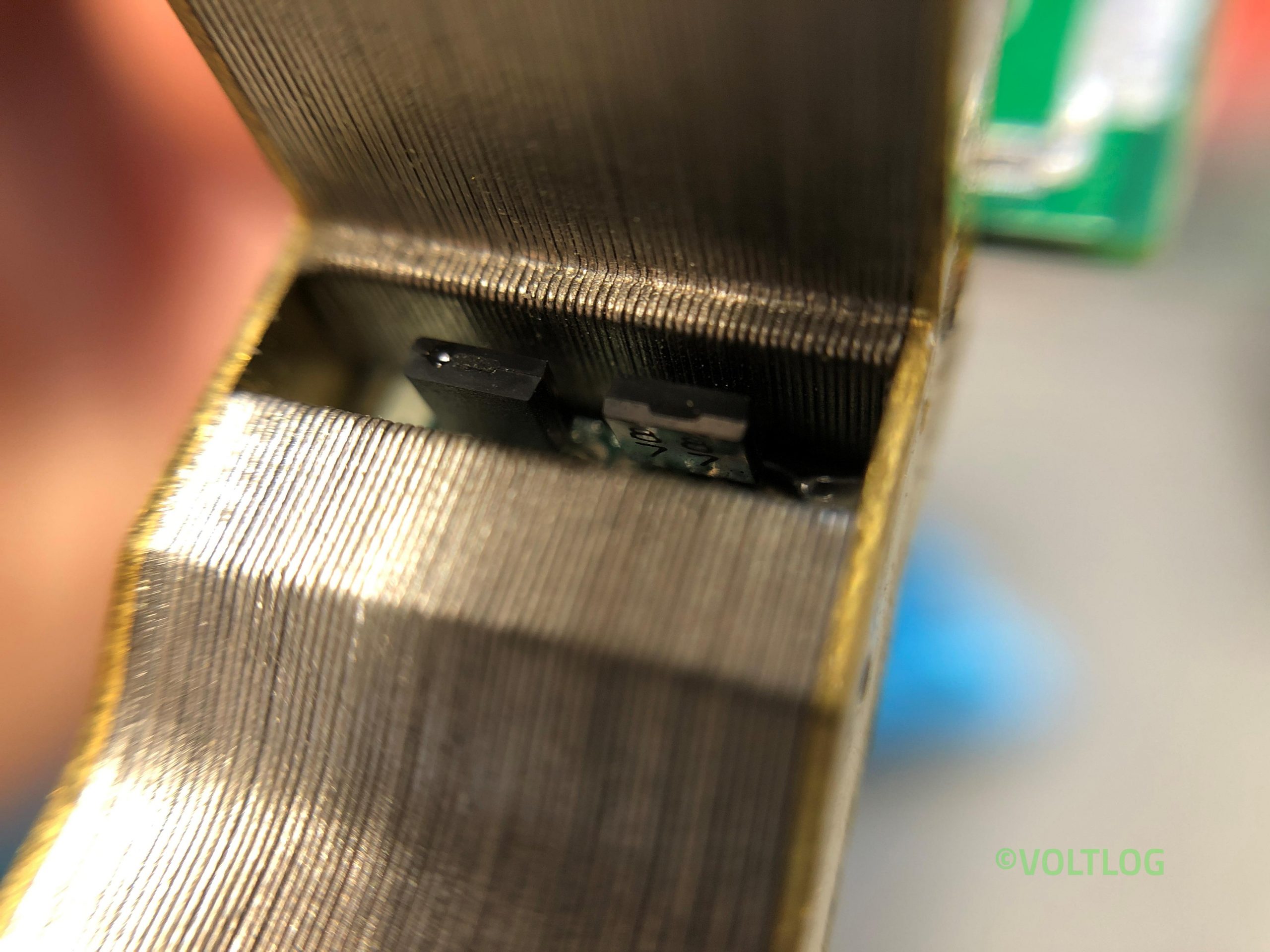
But there are still a lot of scenarios where you could use this successfully on the electronics workbench so it might be worth building something like this. I want to make this nicer by building it inside an enclosure with the required bnc connector for connecting to the oscilloscope and 4mm banana plugs for passing the current through. I picked this small aluminium enclosure which would be enough to house the resistor, actually the resistors, because there are several advantages to using multiple resistors in parallel.
Alternative to this simple shunt resistor measuring method include the Joulescope which is a fully featured dc energy measurement test instrument with incredibly wide dynamic range that allows you to capture the smallest currents next to a jump to a higher current. I reviewed the Joulescope in Voltlog #211.
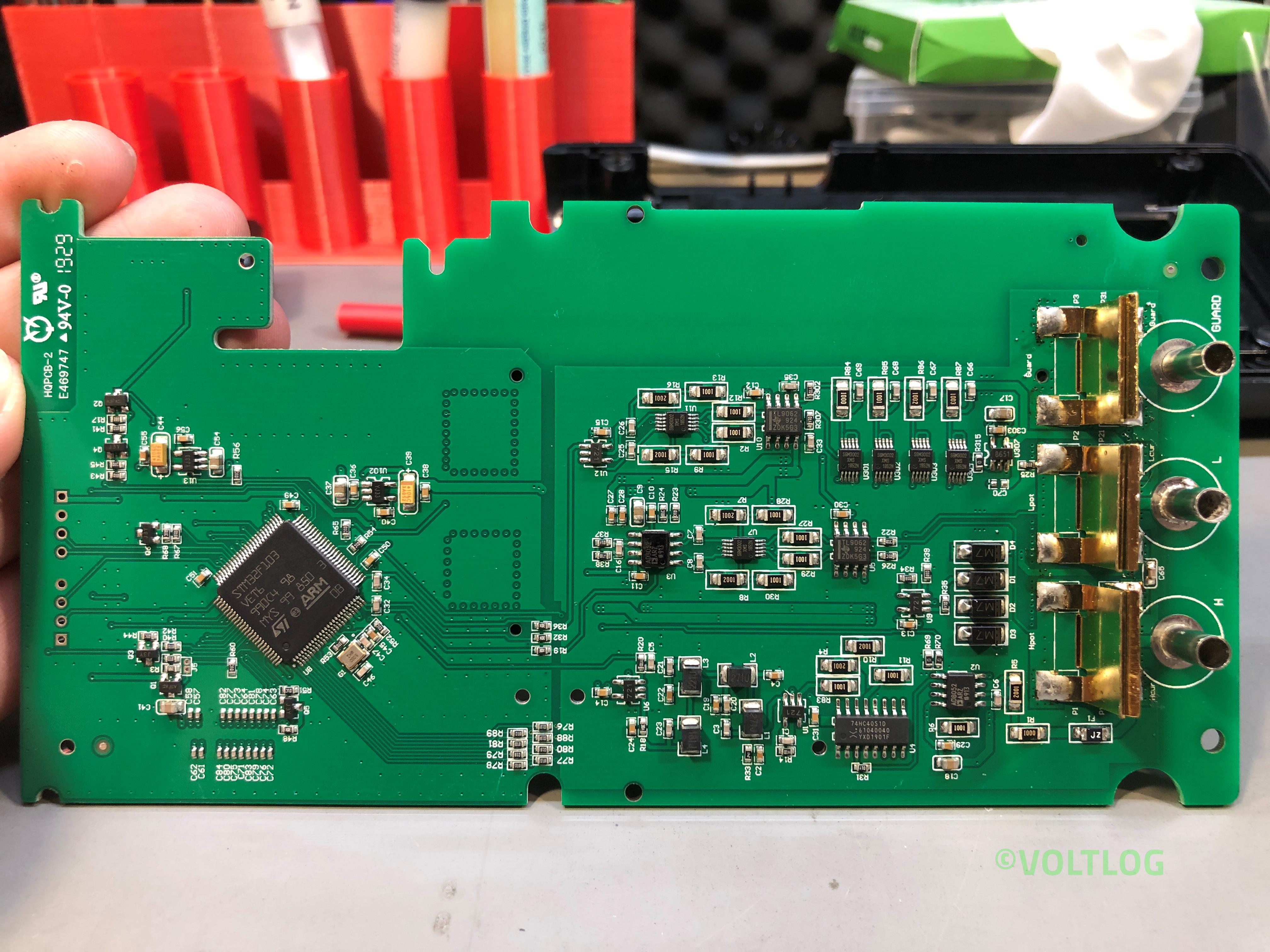
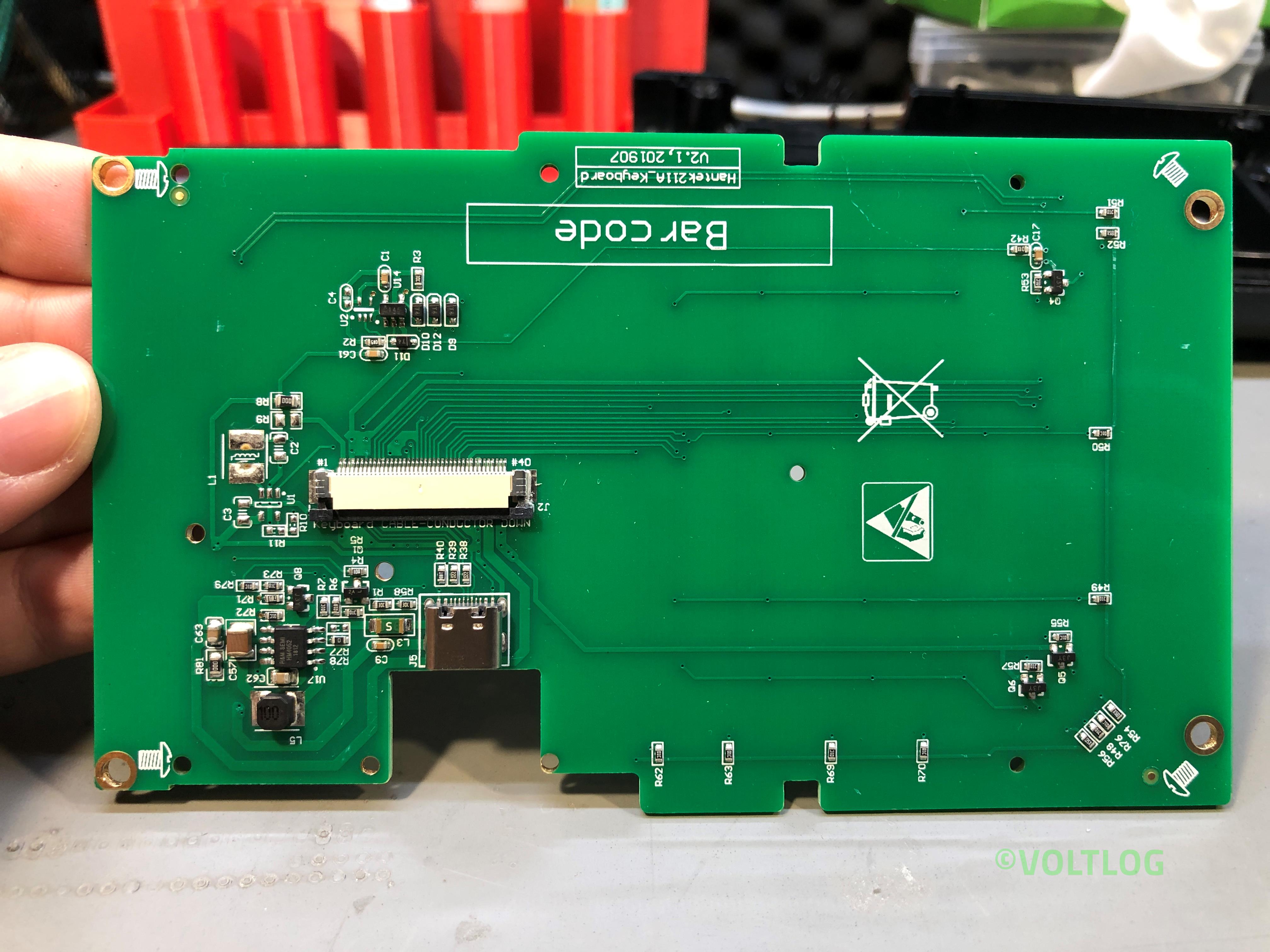
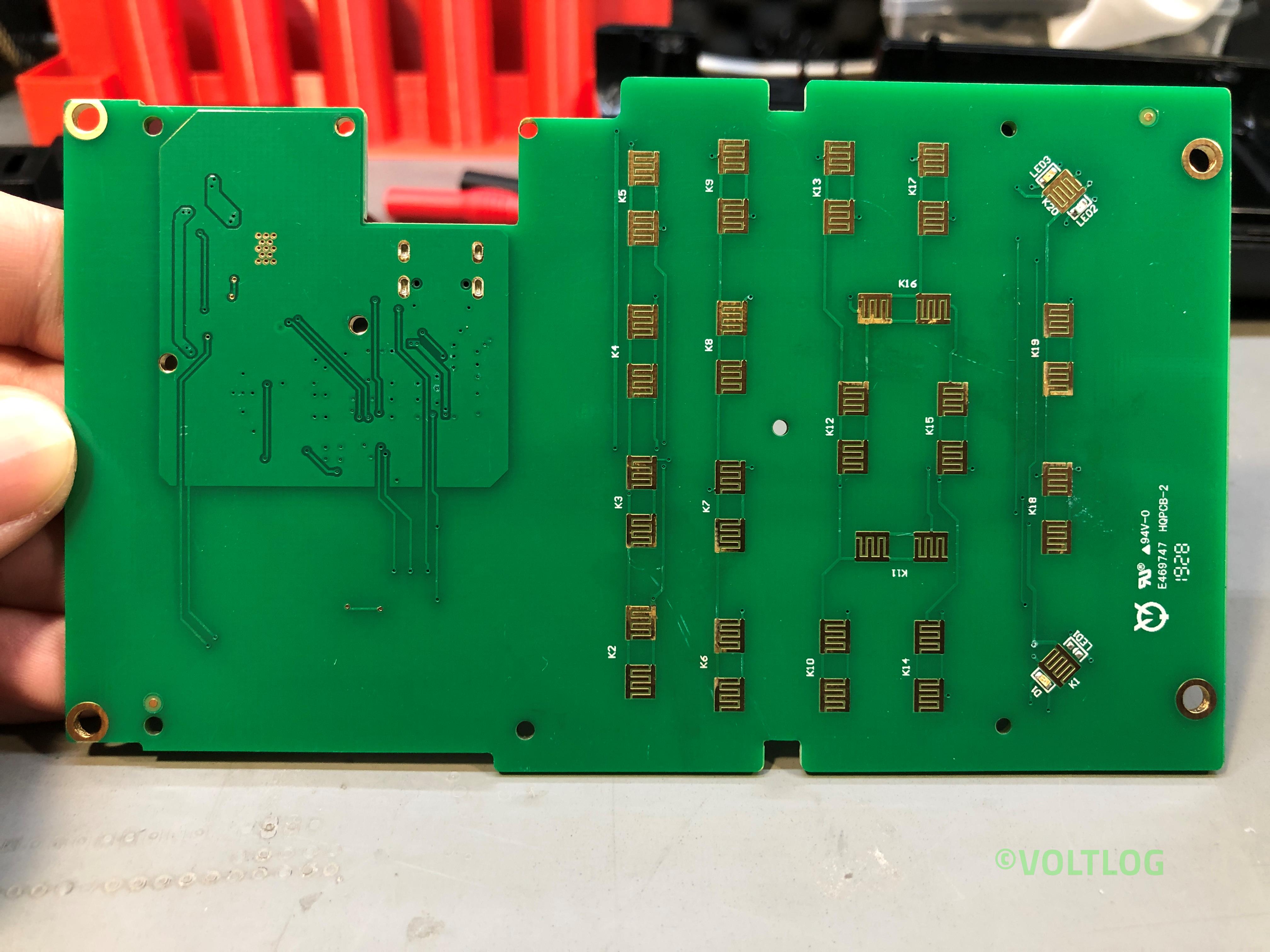
Hantek TO11 1832C LCR Meter Review & Teardown | Voltlog #303
I never really had any professional LCR meter in my lab so far, I’ve only done measurements using this transistor tester which also features a rudimentary LCR function but that’s about to change because today we’ll be taking a close look at the Hantek TO11 handheld LCR meter.
There are two models for this LCR meter TO11 and TO22 and as far as I can tell the only advantages the more expensive TO22 model has are the extended test frequency range up to 100KHz and a second option for test voltage at 0.3V.
Next let’s mention the naming confusion, there is something going on with the naming of this instrument and I can’t quite figure it out. On hantek’s website you can find this LCR meter listed as model number 1832C and 1833C while I suspect all newer units are marked TO11 and TO22 respectively. I’ve emailed Hantek and asked them to clarify this and confirm whether or not there are any differences and why the two names and they replied saying the two are basically the same, the TO11 being an ODM version.
Here are some images captured during the teardown, click on the thumbnails to get a high resolution image of the LCR Meter internal PCBs.
Kunkin KP184 Electronic Load Issues Fixed | Voltlog #302
In this video I’m going to address the issues I found with the Kunkin KP184 electronic load during the review and teardown of the unit but also some issues people mentioned in the comments. There are 7 things I would like to address in total:
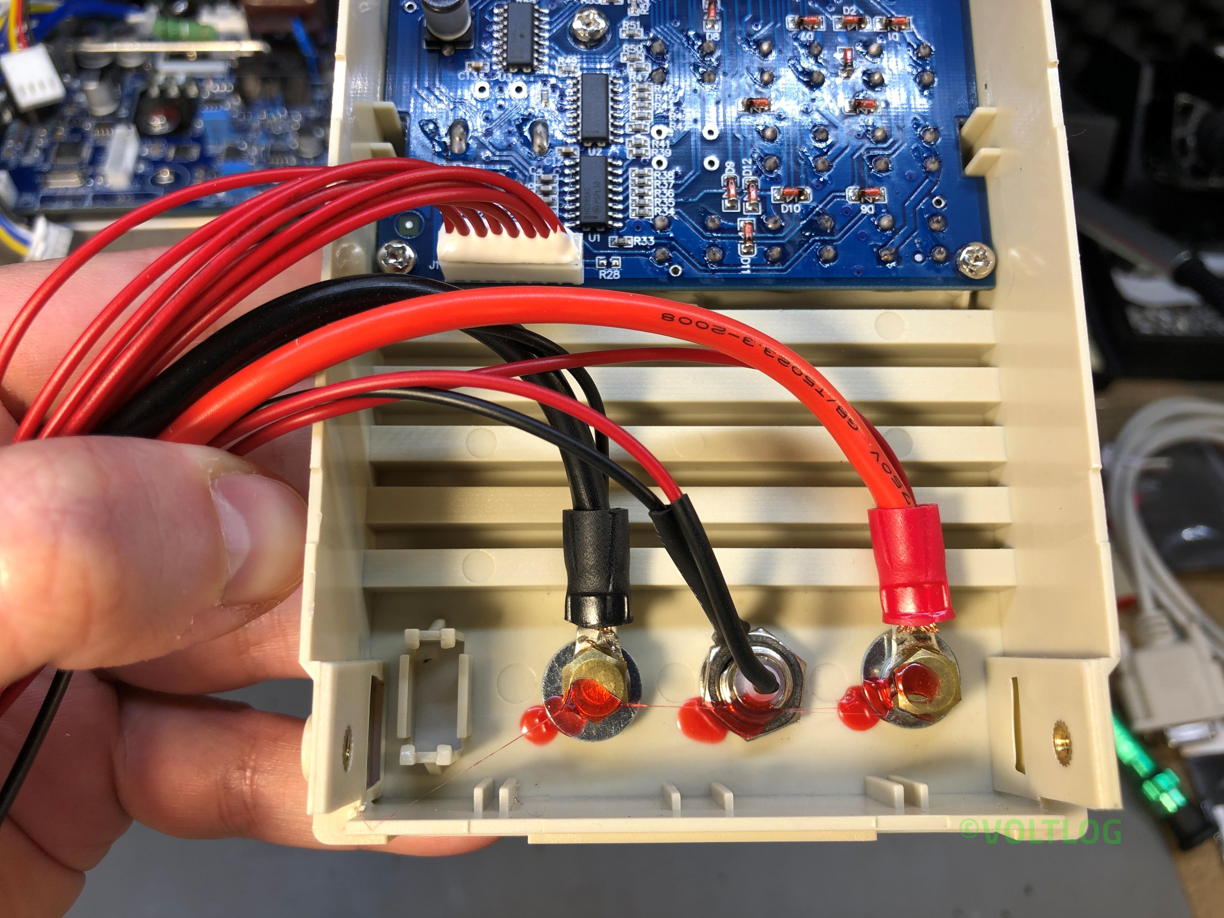
- Binding post internal diameter issue.
- Grounding issue with blue metal enclosure.
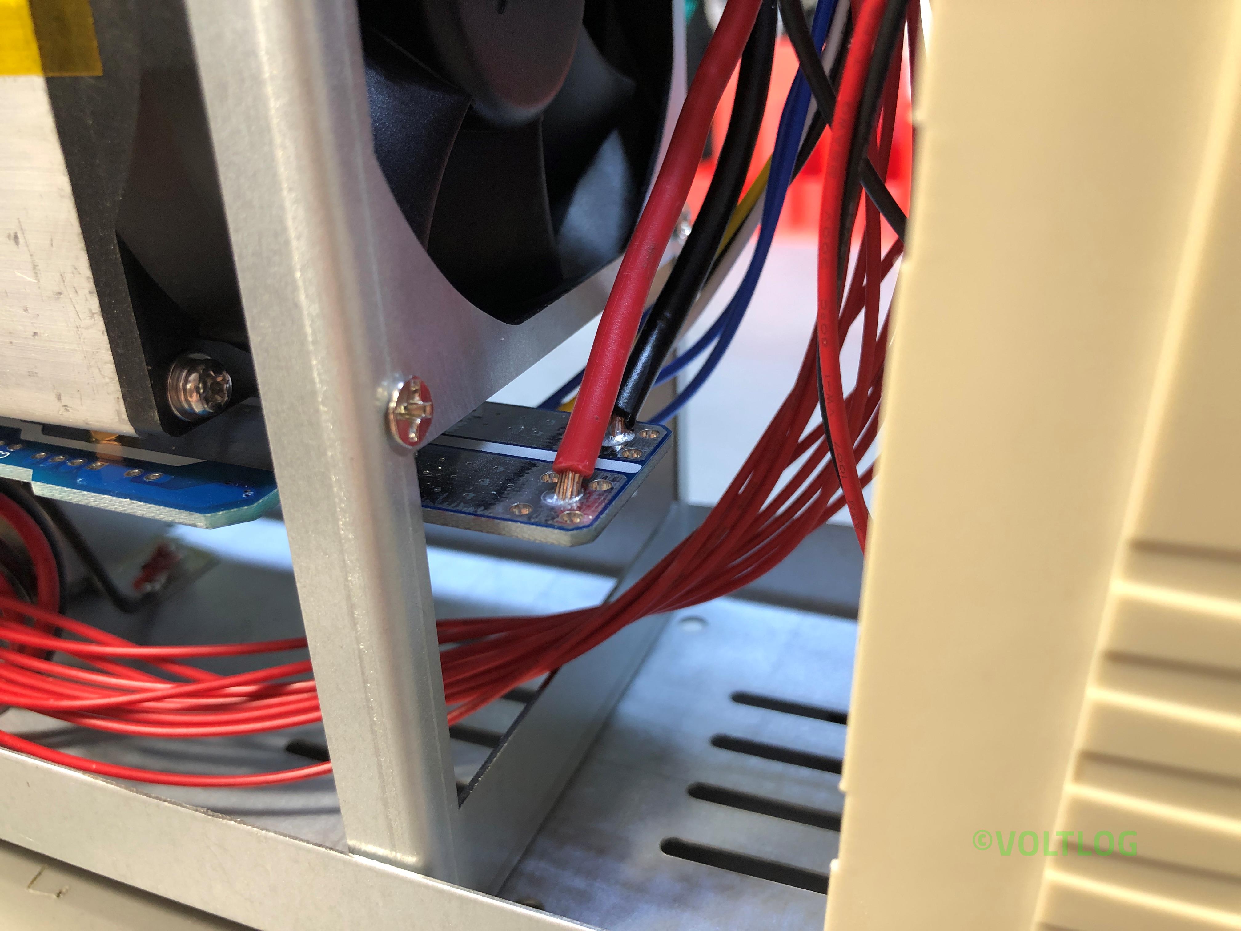
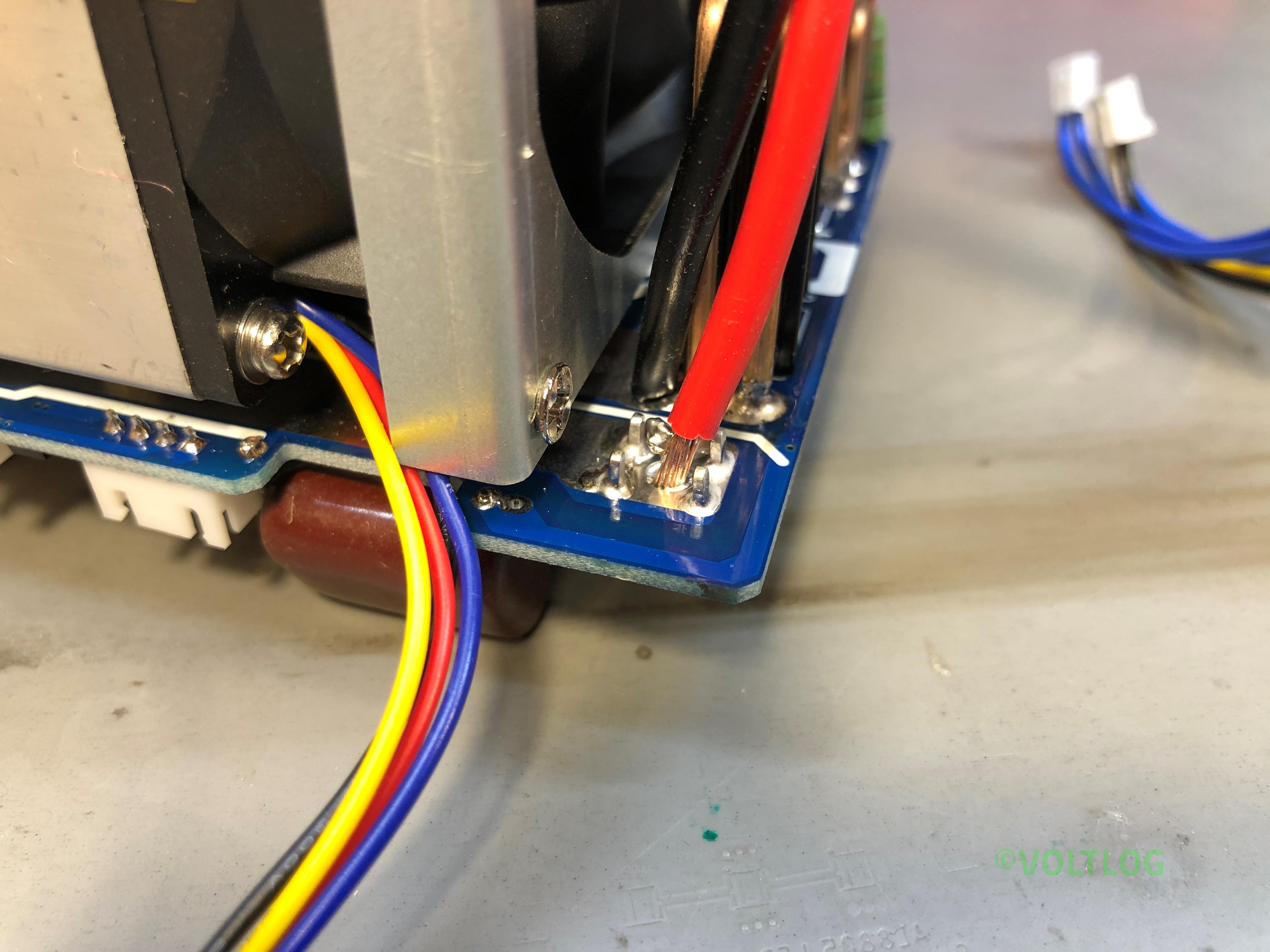
- Bad solder joints on thick wires coming to mainboard.
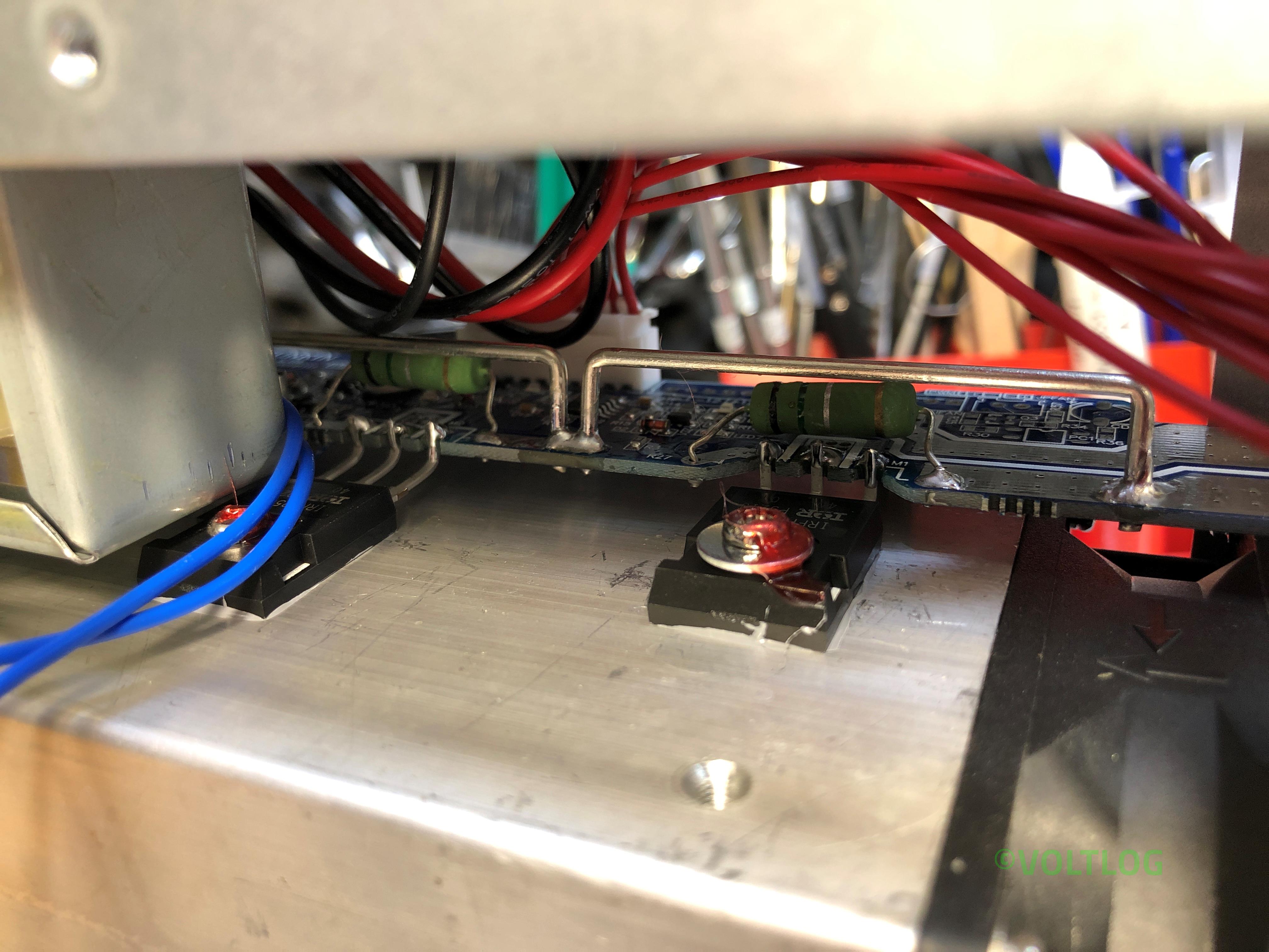
- IRFP250M mosfet safe operating area, fake or genuine?
- Supposed bug in tripping over-power protection.
- Supposed noise in constant current mode loop.
- Calibration procedure.
Nothing changes in terms of this being the best electronic load you can buy in this price range, II like it and I highly recommend it if you need to test power supplies or batteries, I think you will be pleased with this unit. If you would like to see the review or the teardown video I will link those on screen right now so you just have to click somewhere in this area. As always thank you for watching and don’t forget you can support this channel on Patreon.
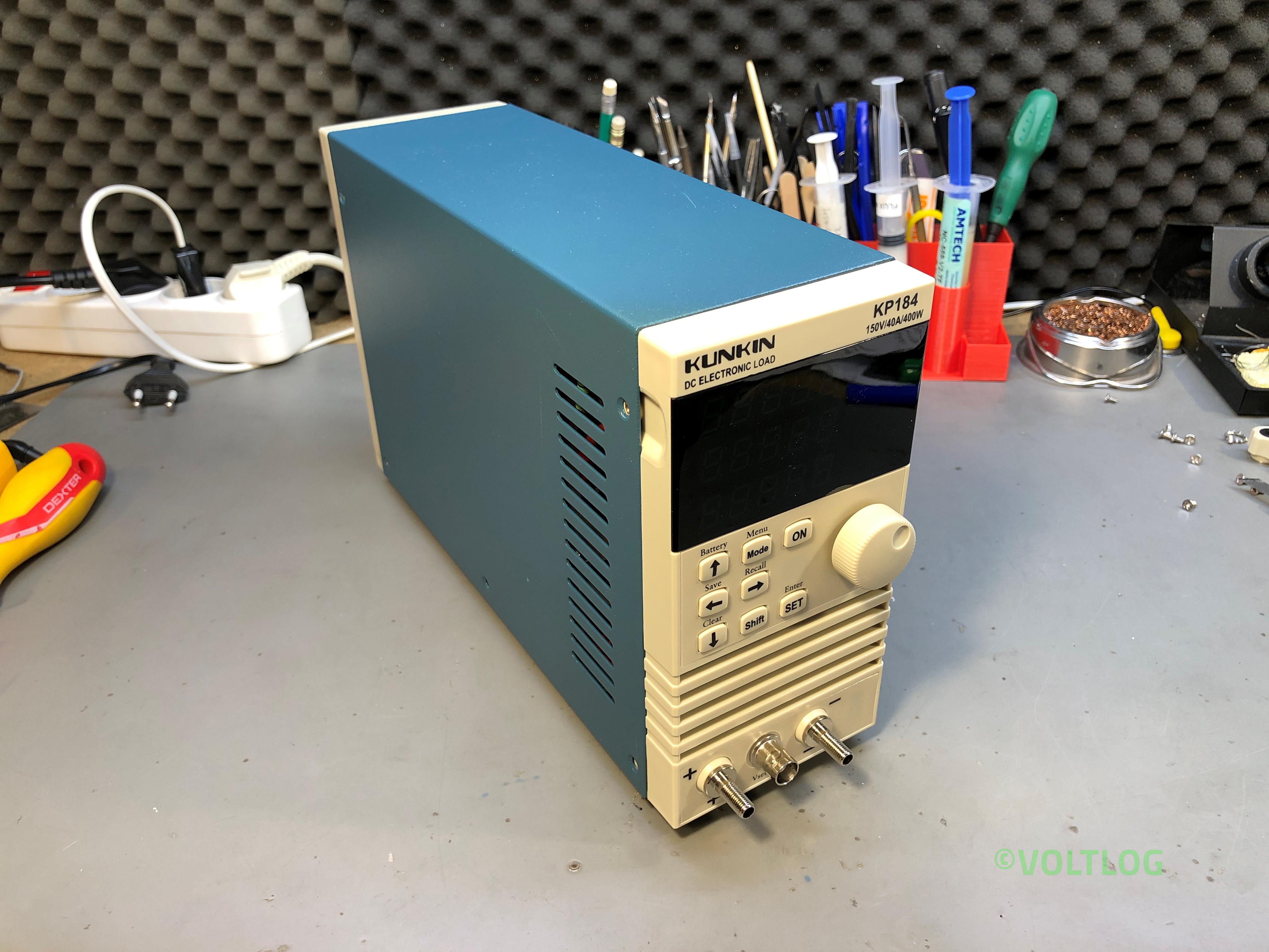
Best Affordable Electronic Load – Kunkin KP184 Teardown | Voltlog #300
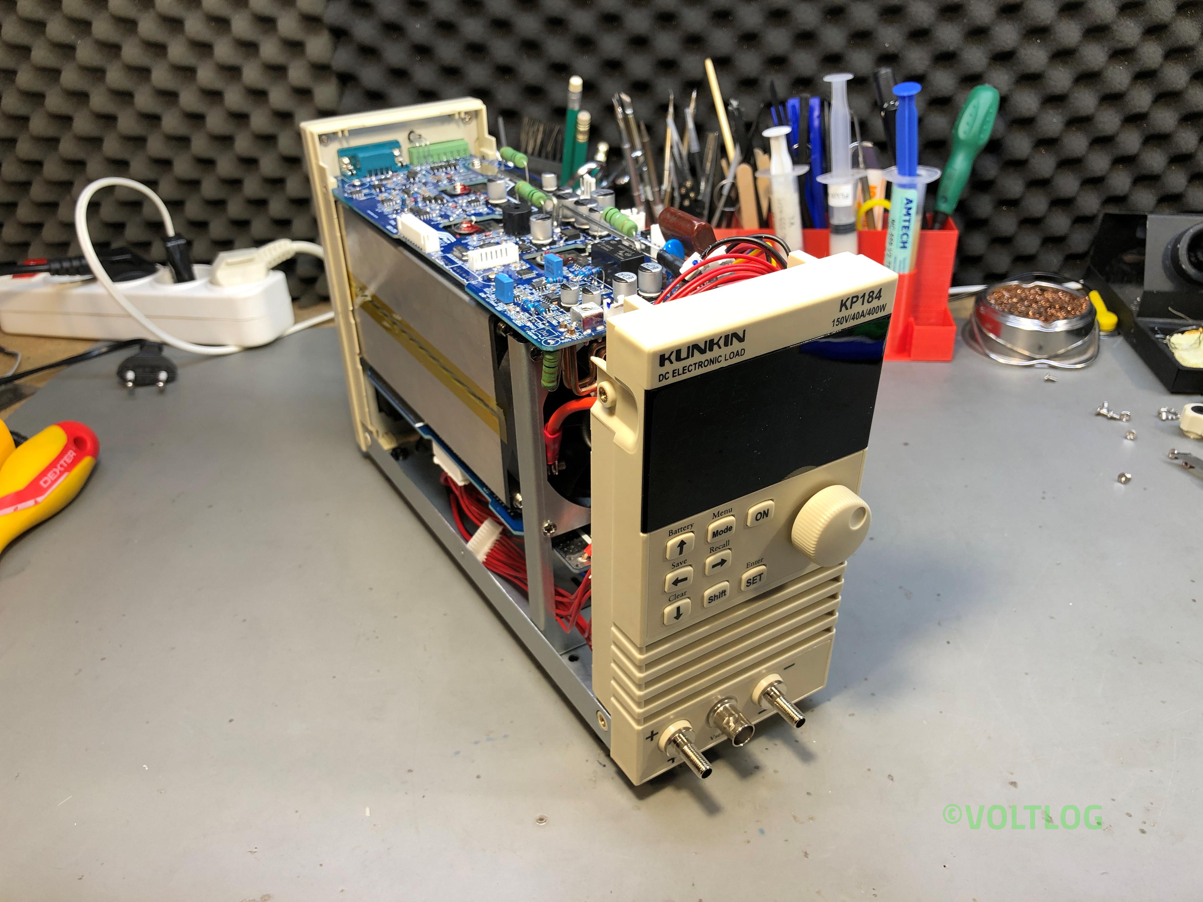
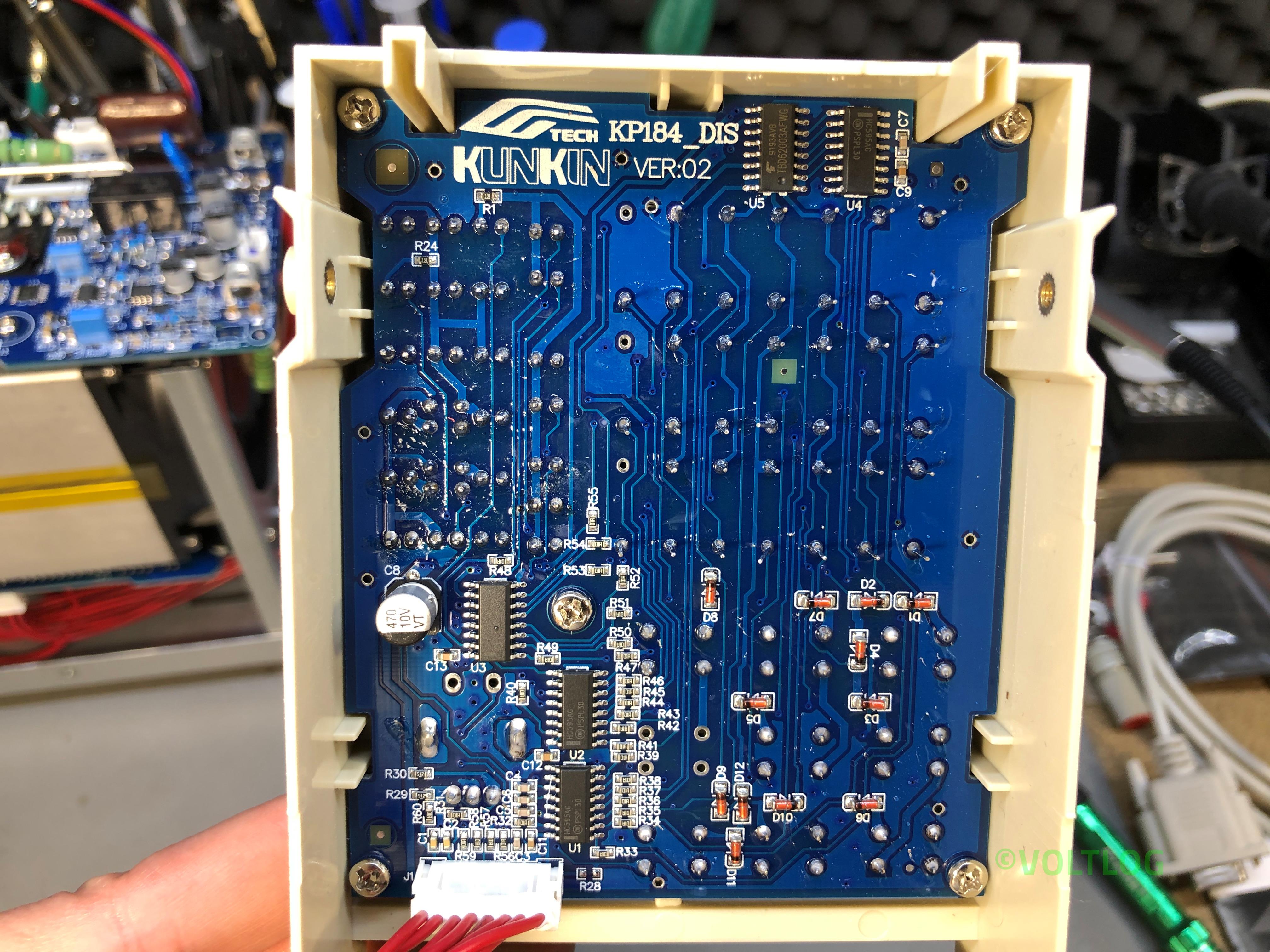
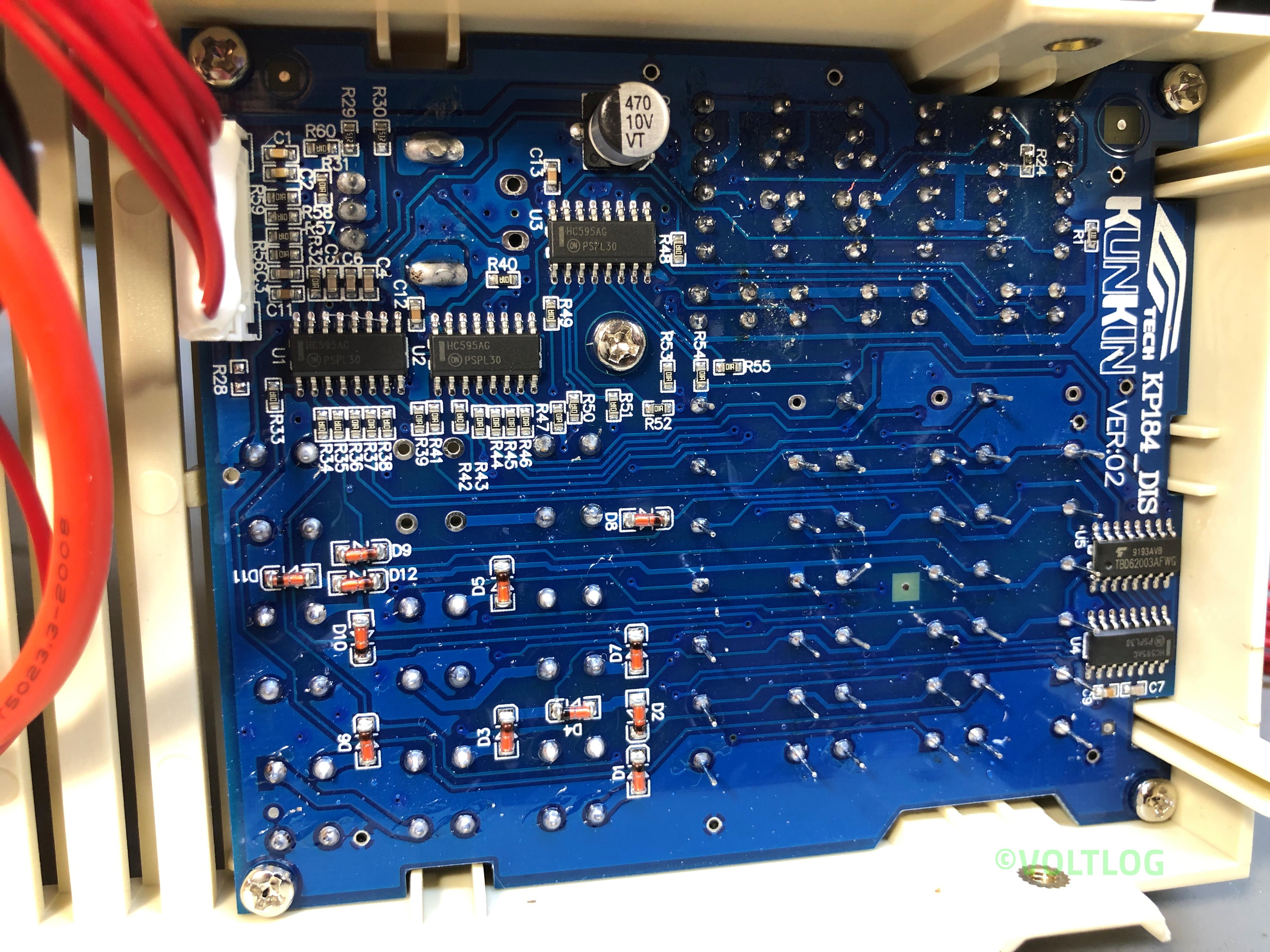
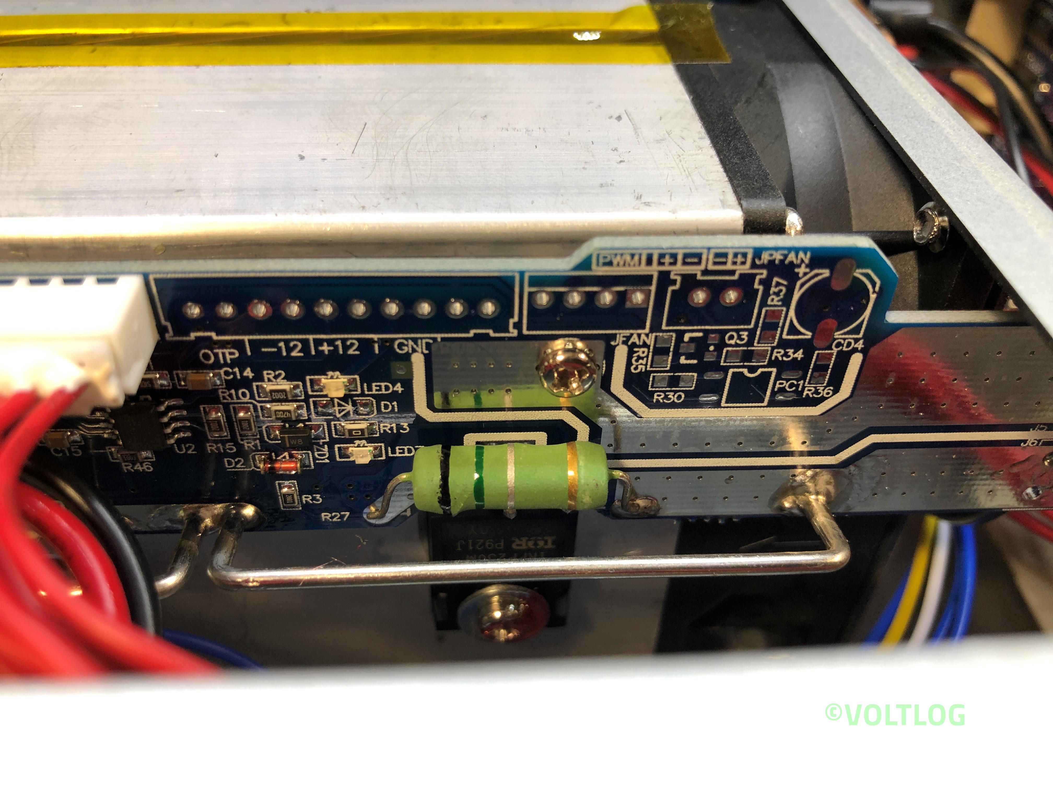
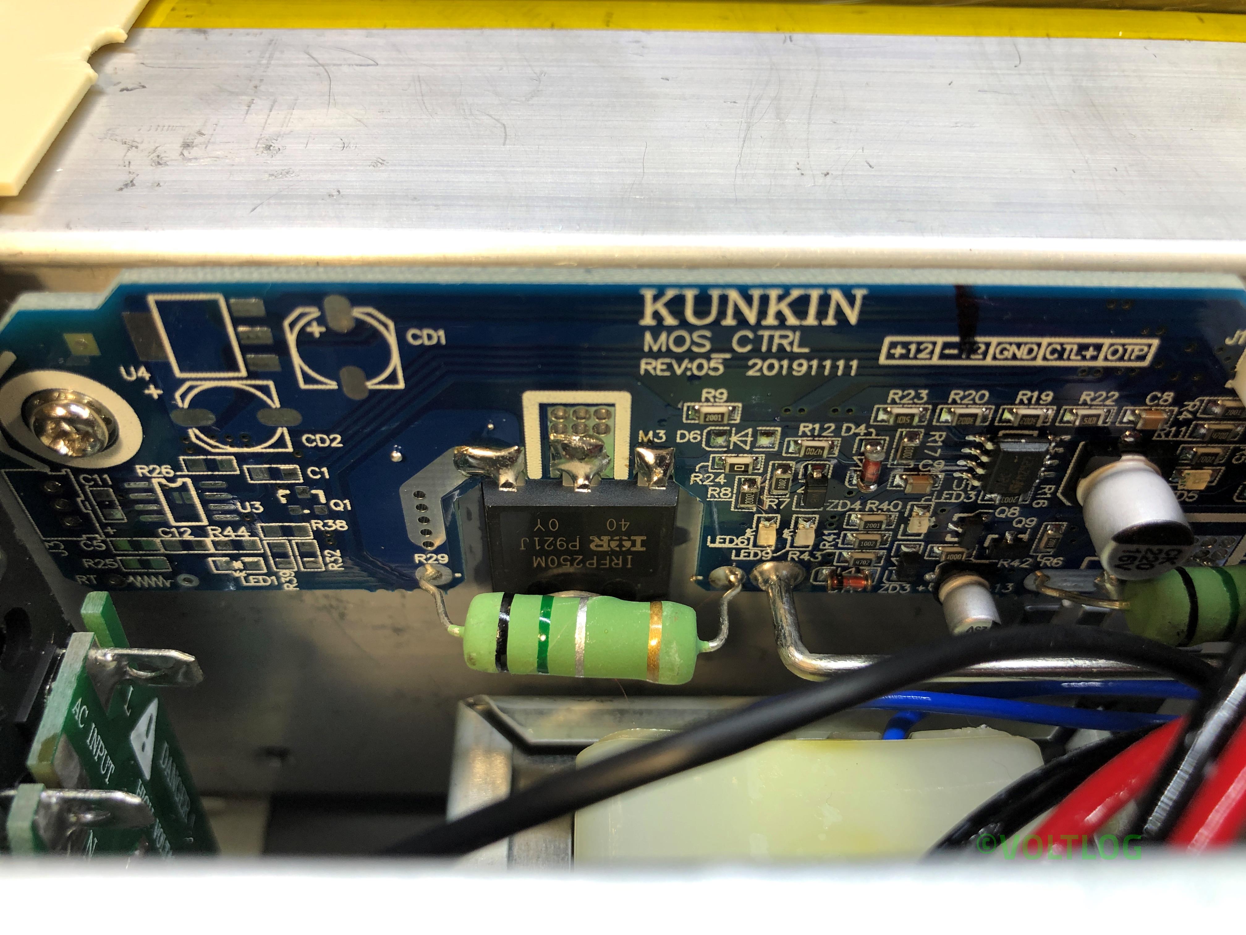
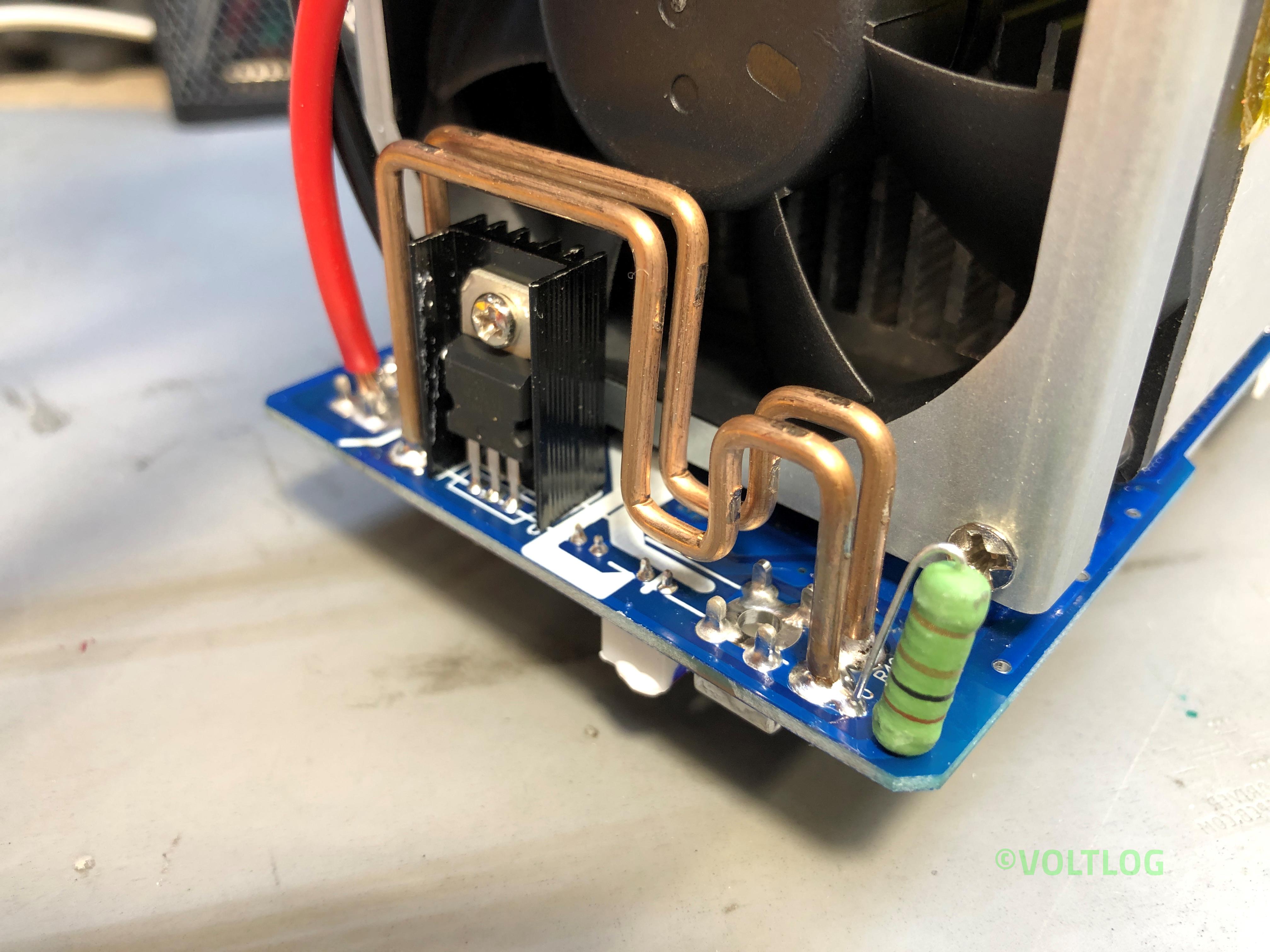
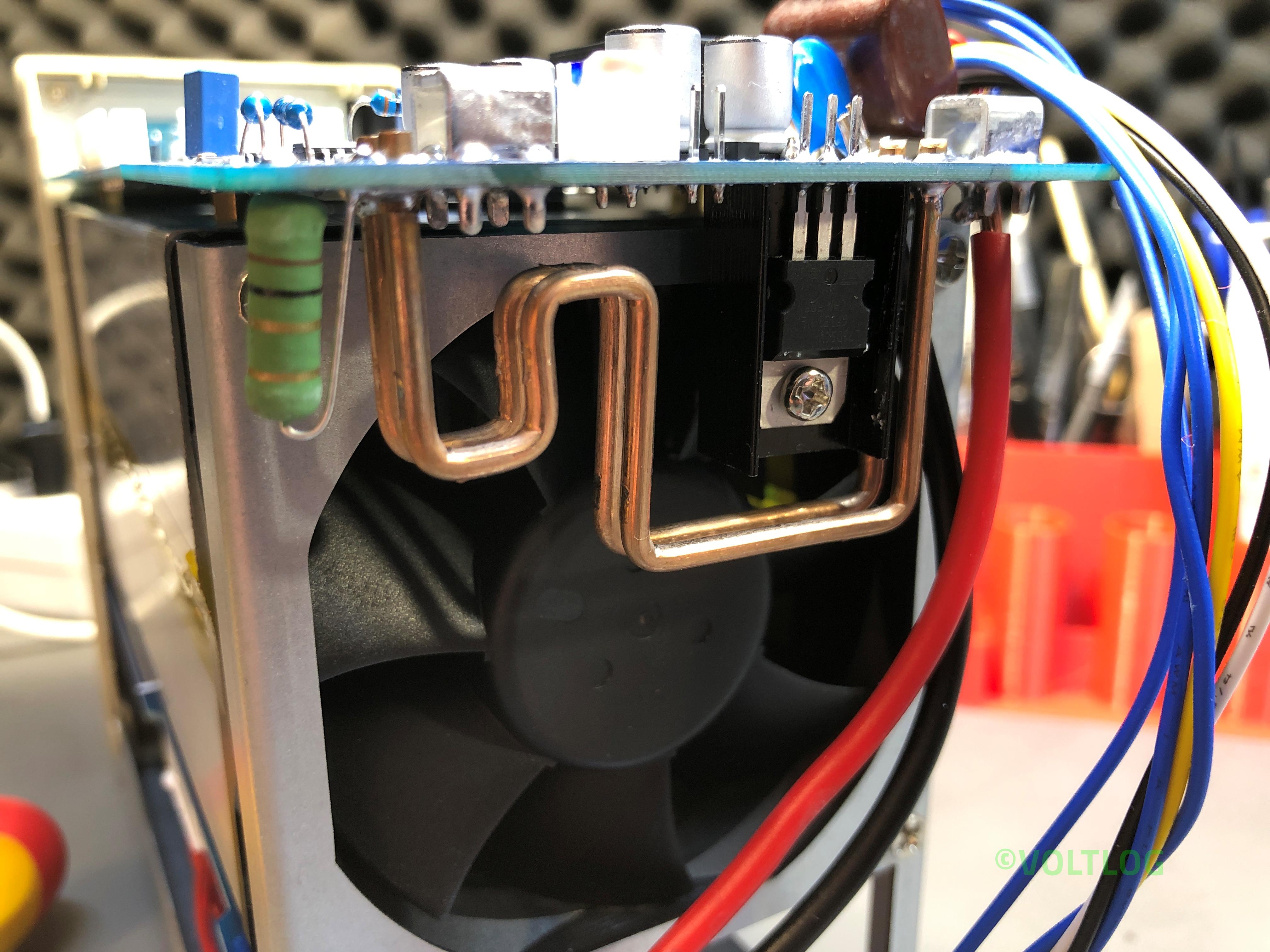
In the previous video I reviewed the KP184 electronic load, I showed you all the features it has, I tested the accuracy of the front panel meter but the video was getting quite long and I skipped the teardown for a future video. Well, this is it, it looks like we have a bunch of screws that have to be removed to slide the folded metal cover off.
As you may remember from the previous video I discovered something related to wiring & safety, the earth wire was connected to the bottom part of the enclosure but it wasn’t connected to this blue cover which is also metallic. Now we can see why, this has a thick coat of paint so we can fix this by either scraping the paint away in the area where this makes contact with the bottom part or we could add a separate earth wire which would probably be a more reliable way to fix this.
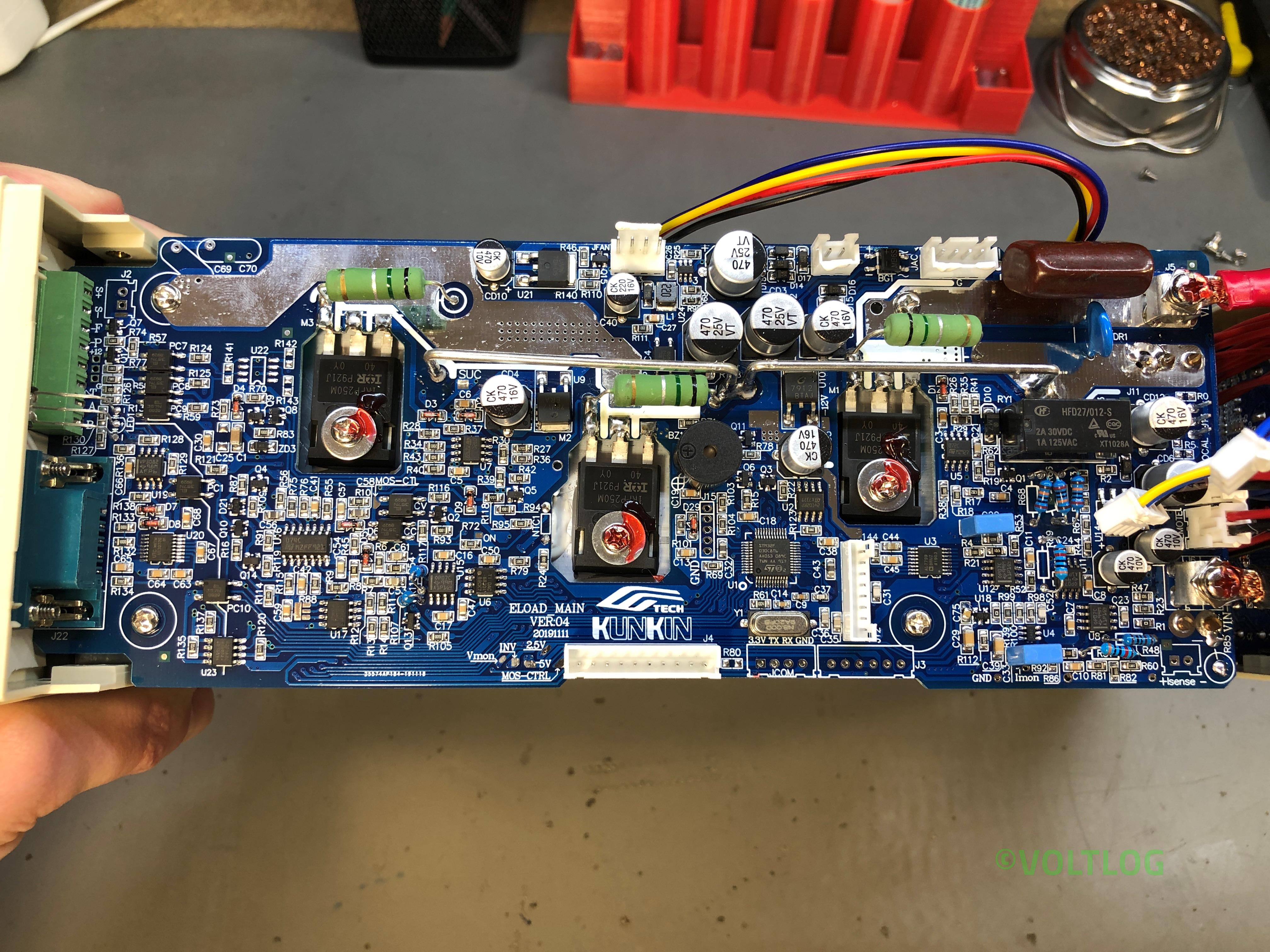
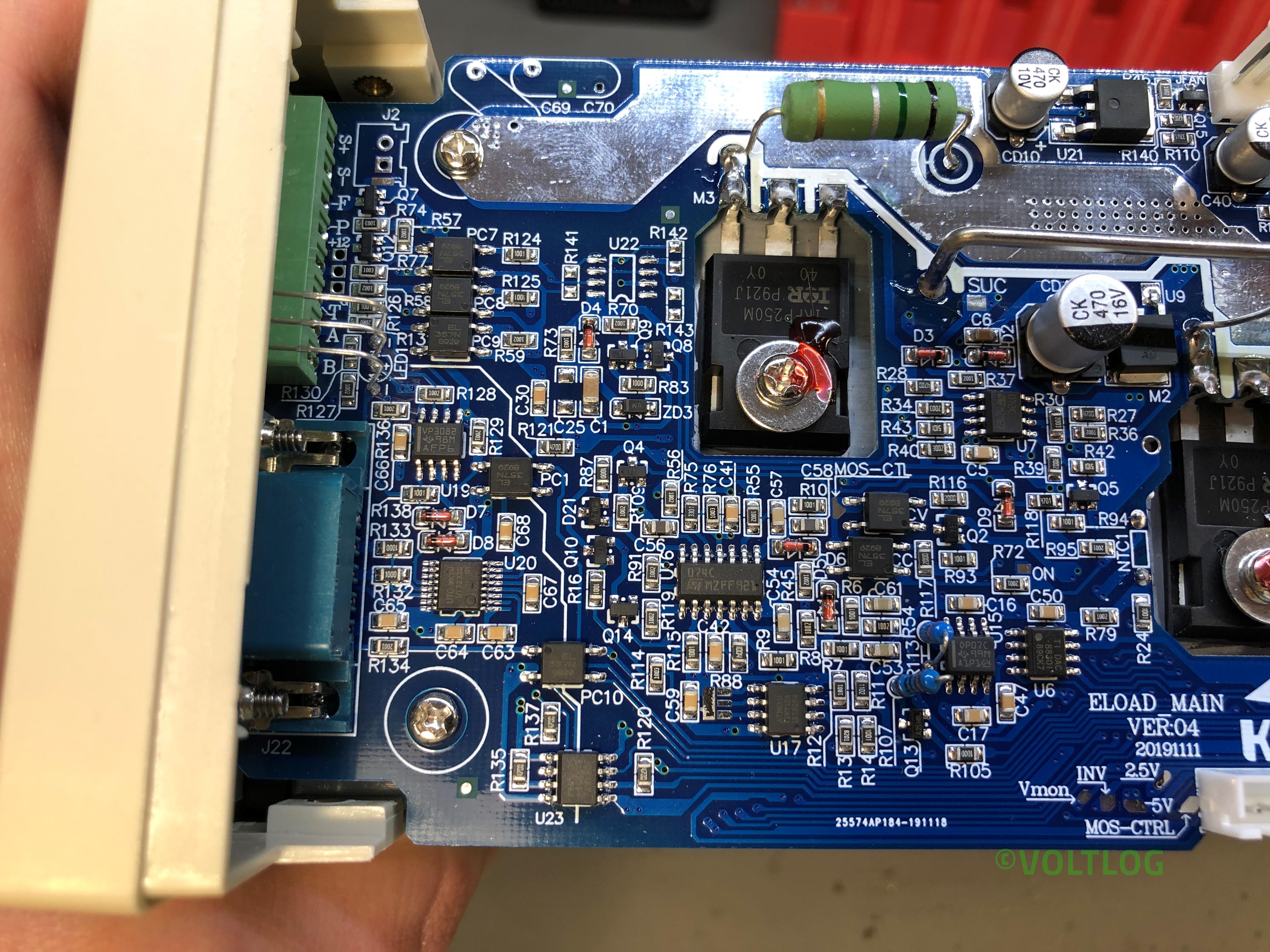
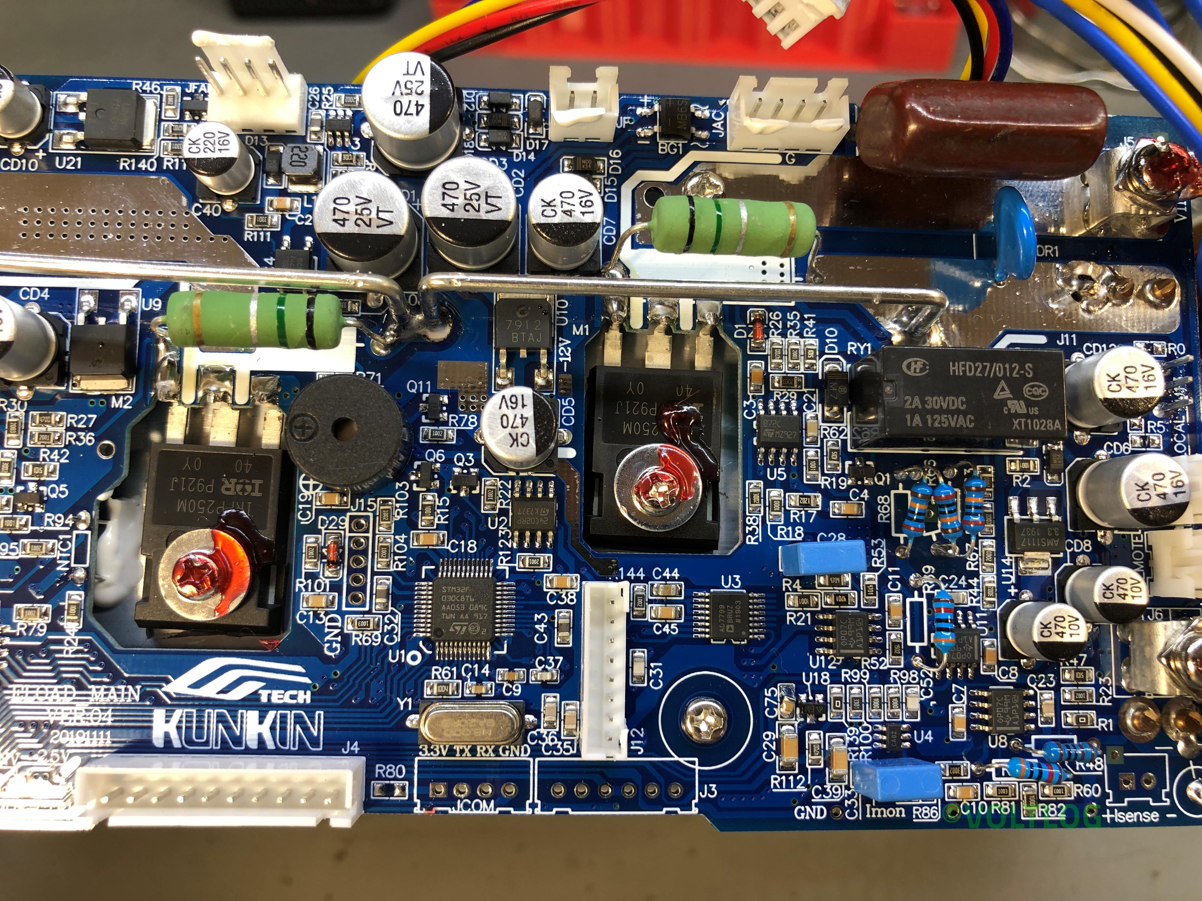
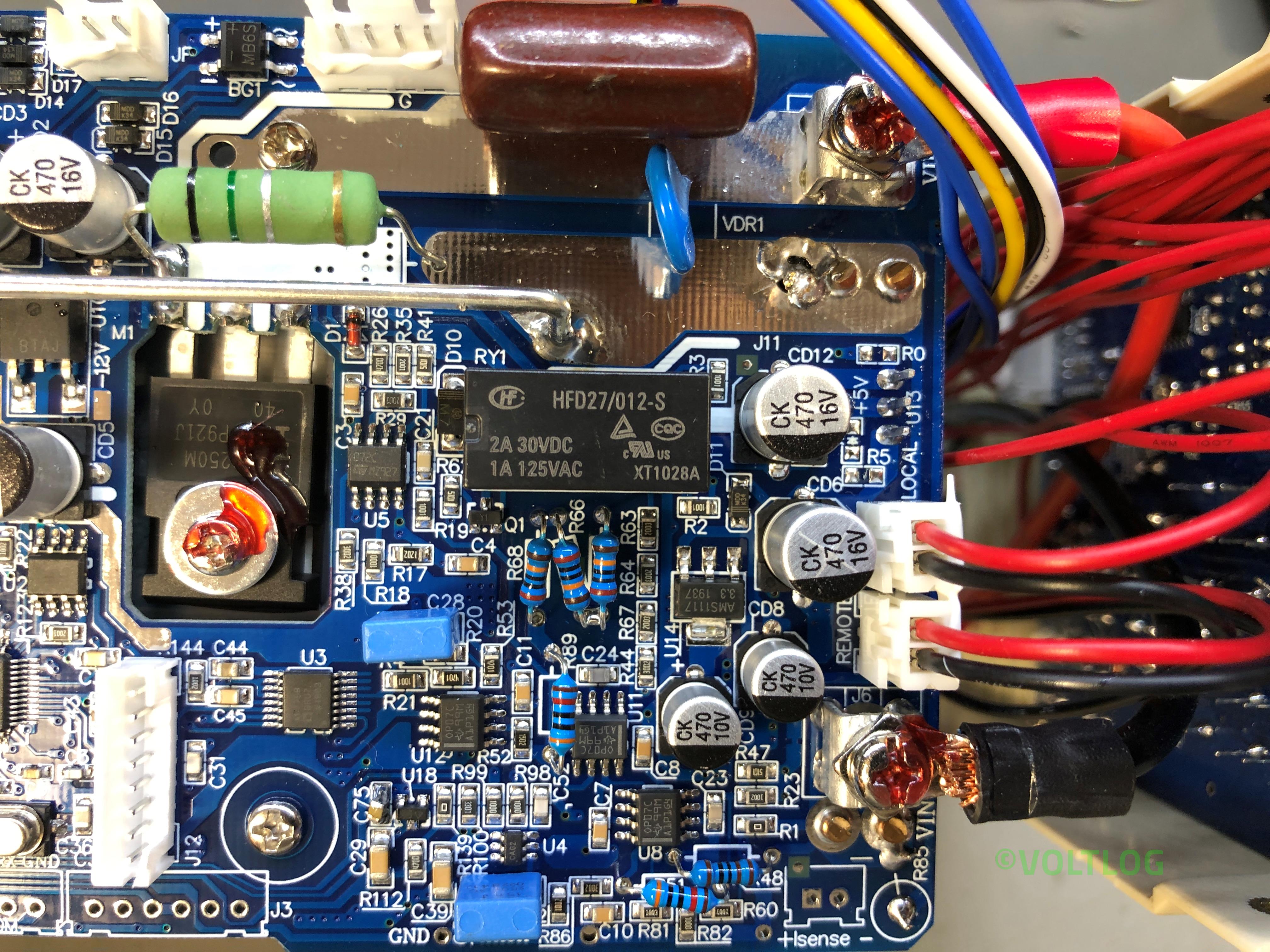
The first thing I’m noticing is the silkscreen, this board is version 04 and has a date code of November 2019. And there are a bunch of other nicely placed labels for various signals throughout the board. Soldering looks to be nice and clean with the exception of these thick wires coming from the bottom board, which in this particular joint looks like it hasn’t flowed sufficiently, I will have to fix that later. Wires are nicely secured with adhesive to their end connectors and apart from these thick wires coming from the bottom board everything has connectors which makes it easy to disassemble and service.
Checkout the teardown pictures of the Kunkin KP184 electronic load below