Voltlog #255 – Gophert NPS-1601 Review (possibly the best power supply in this price range)

Welcome to a new Voltlog, those who have been with me since the beginning of this channel, may know the first video I ever released, Voltlog #1 was a review of a switch mode bench power supply from Gopher Technology. It was the CPS-3205C and it was a great little unit, it has served me well over the years and I still have it.

At that time I complained about the fact that the unit has the output jacks on the back which is not really convenient for bench use. There were also other issues mentioned while measuring the performance of the power supply,  I will link that video on screen if you want to watch it but the video, audio and editing quality are lower than what you’re seeing today.

Gophert made some improvements to the original design and have now released a newer version of that power supply, it has a new model number it’s NPS-1601 but it’s the same range of 0-32V and 0-5A. There are other models with different ranges but this is what would correspond to the CPS3205 I reviewed years ago.

They have made a bunch of changes on the front panel, the most important one is they moved the output jacks to the front panel so now it’s easier to connect the output of this power supply but they are still not standard spacing so you can’t connect one of these adapters with banana jacks. They have also redesigned the front panel completely, they are still using 7 segment displays but now they also have a wattage display which can be switched on temporarily in place of the amps display, you press the watts button and it will show watts measurement for about 3 seconds before reverting to amps display.

The switch for A/V adjustment is now tactile instead of a sliding switch but the rest has stayed the same. I like this redesigned front panel I just wished they used a lighter color for the text, because for example there are some markings which are barely visible next to the LEDs.

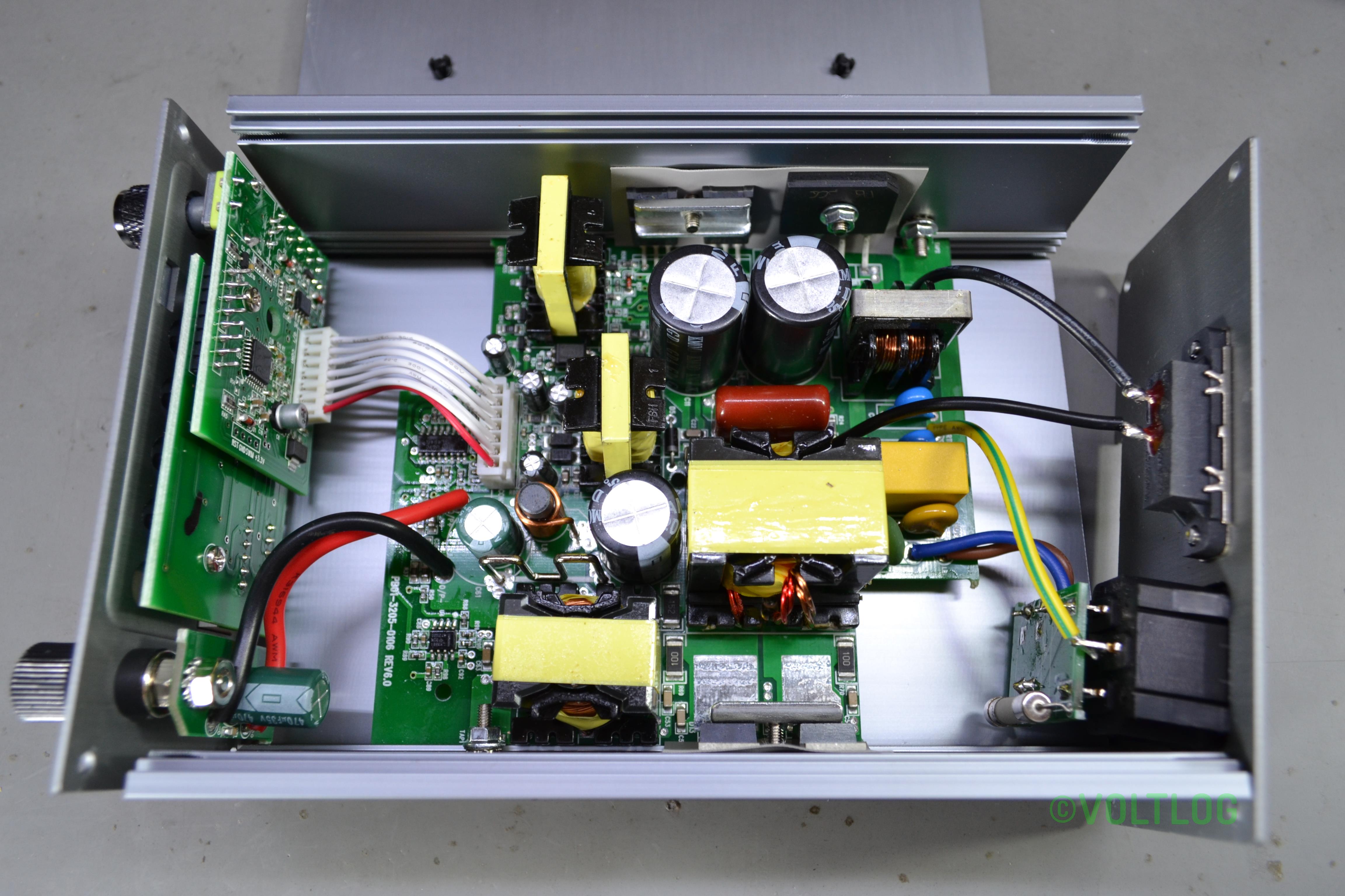
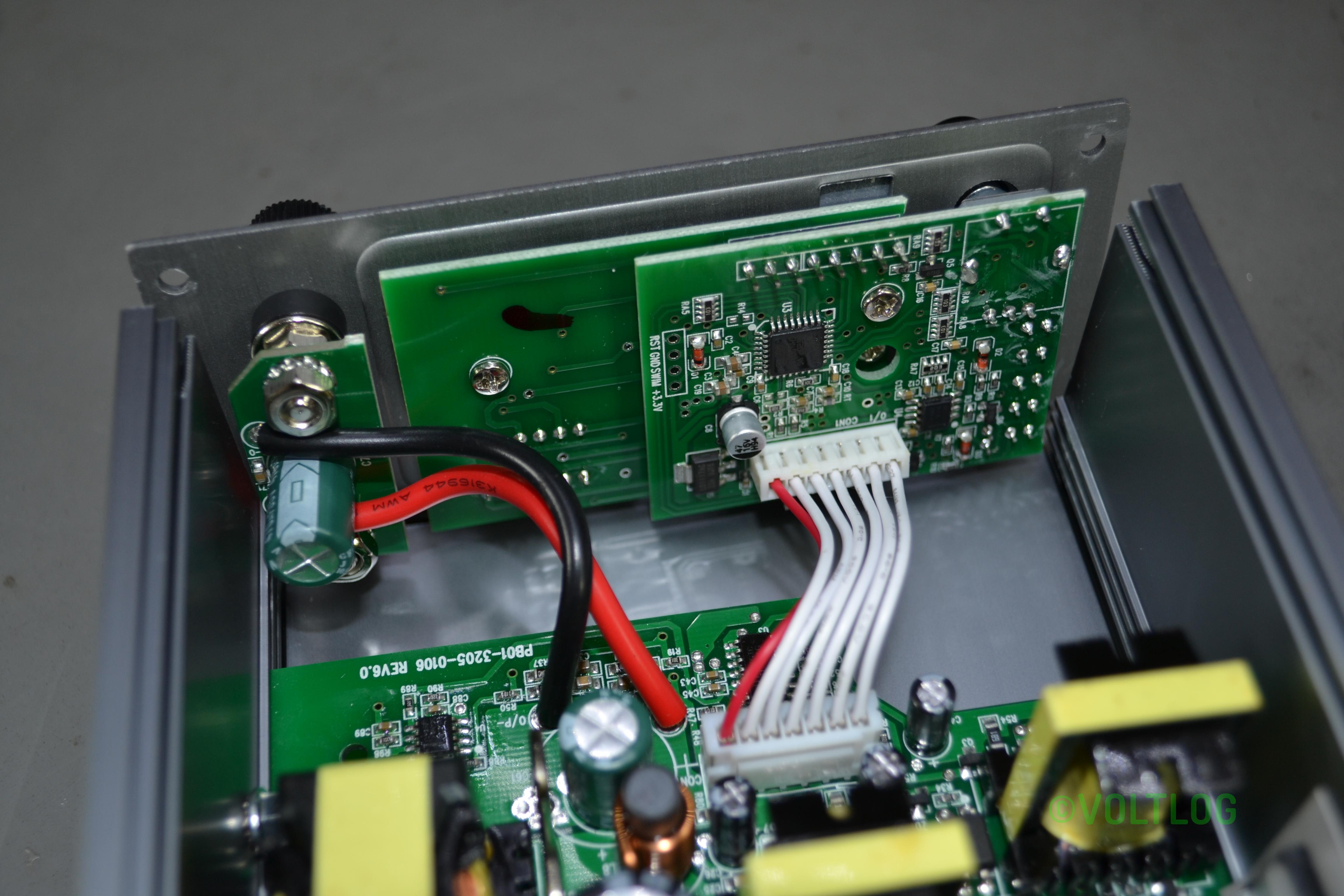
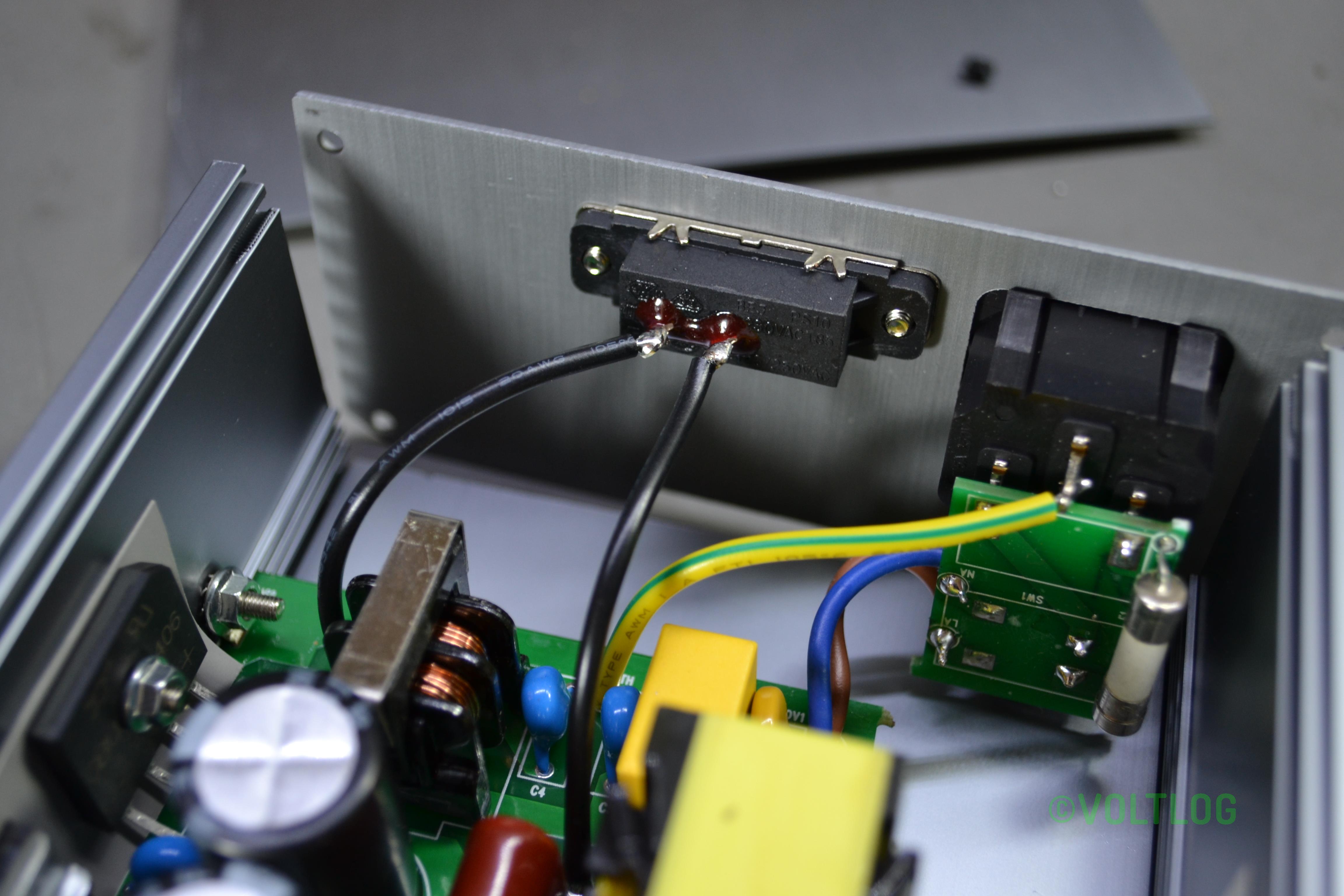
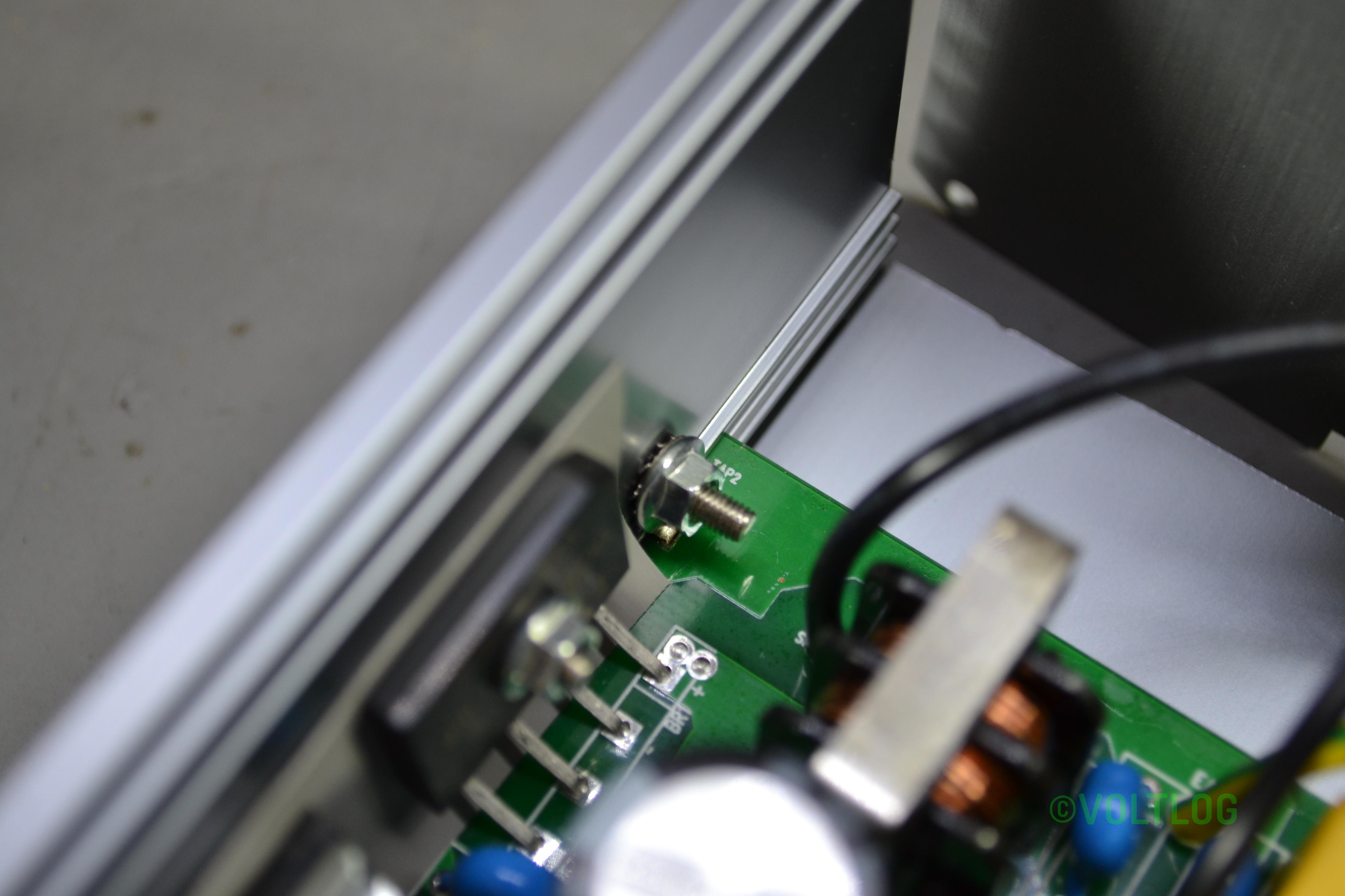
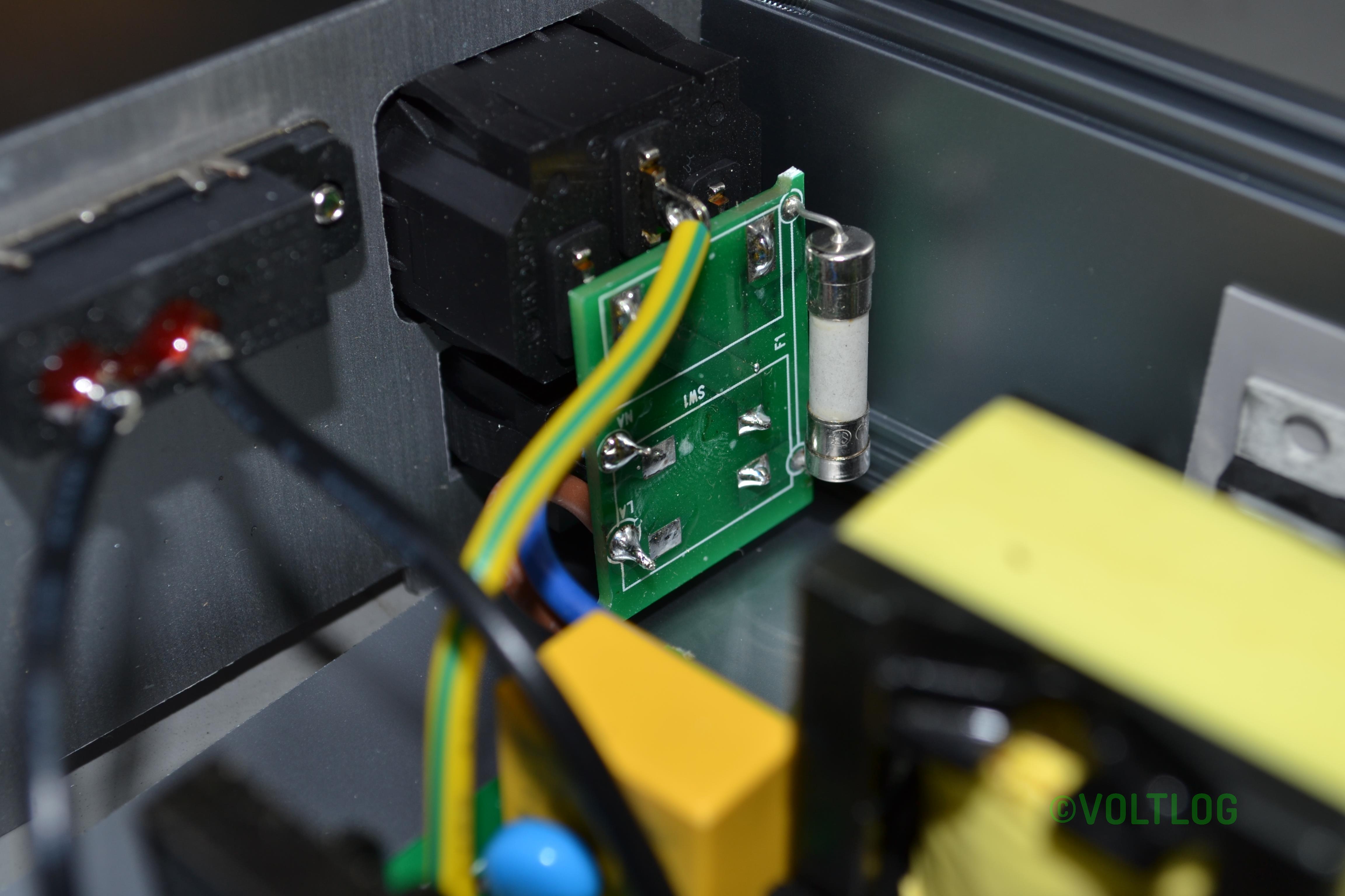
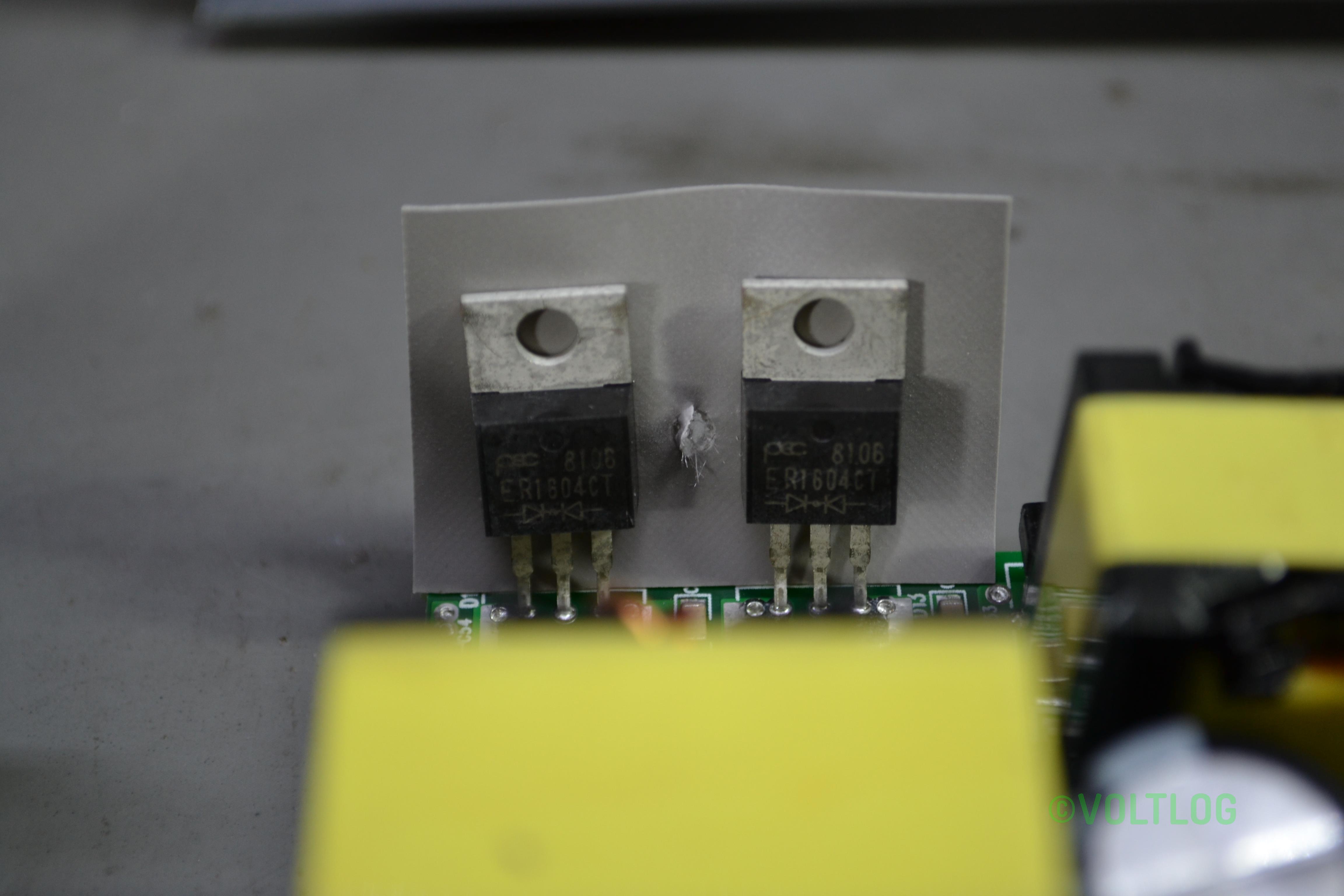
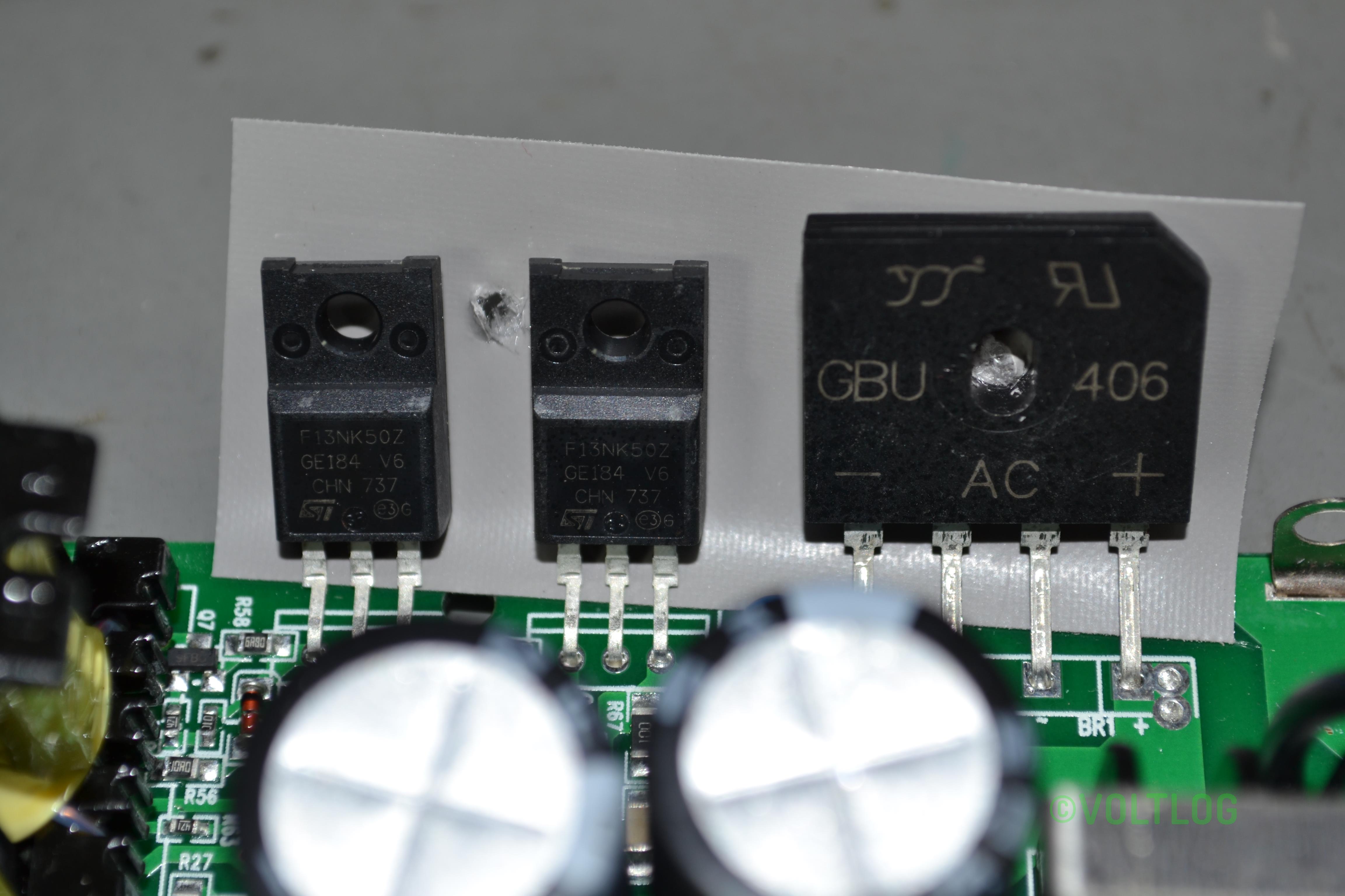
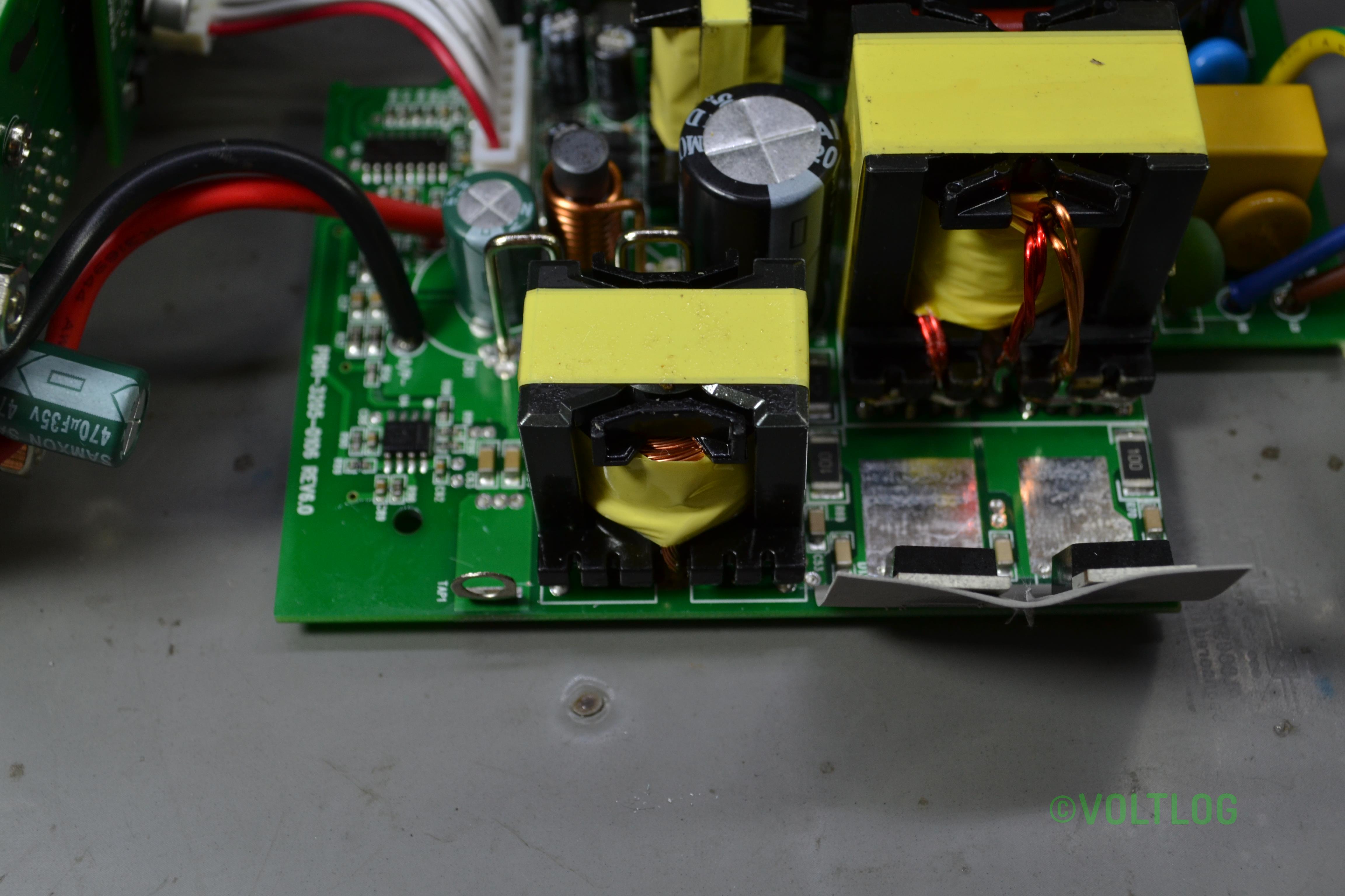
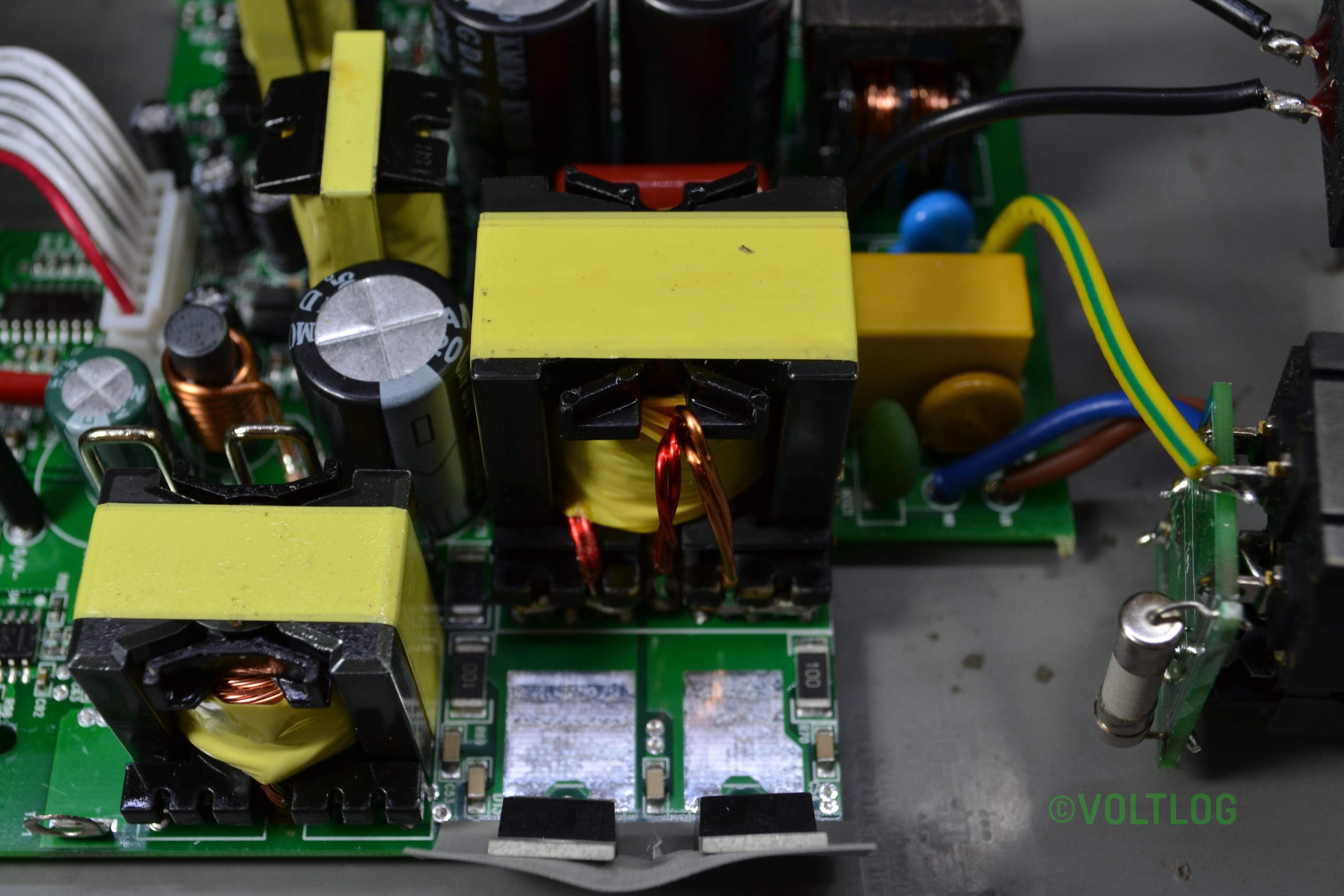
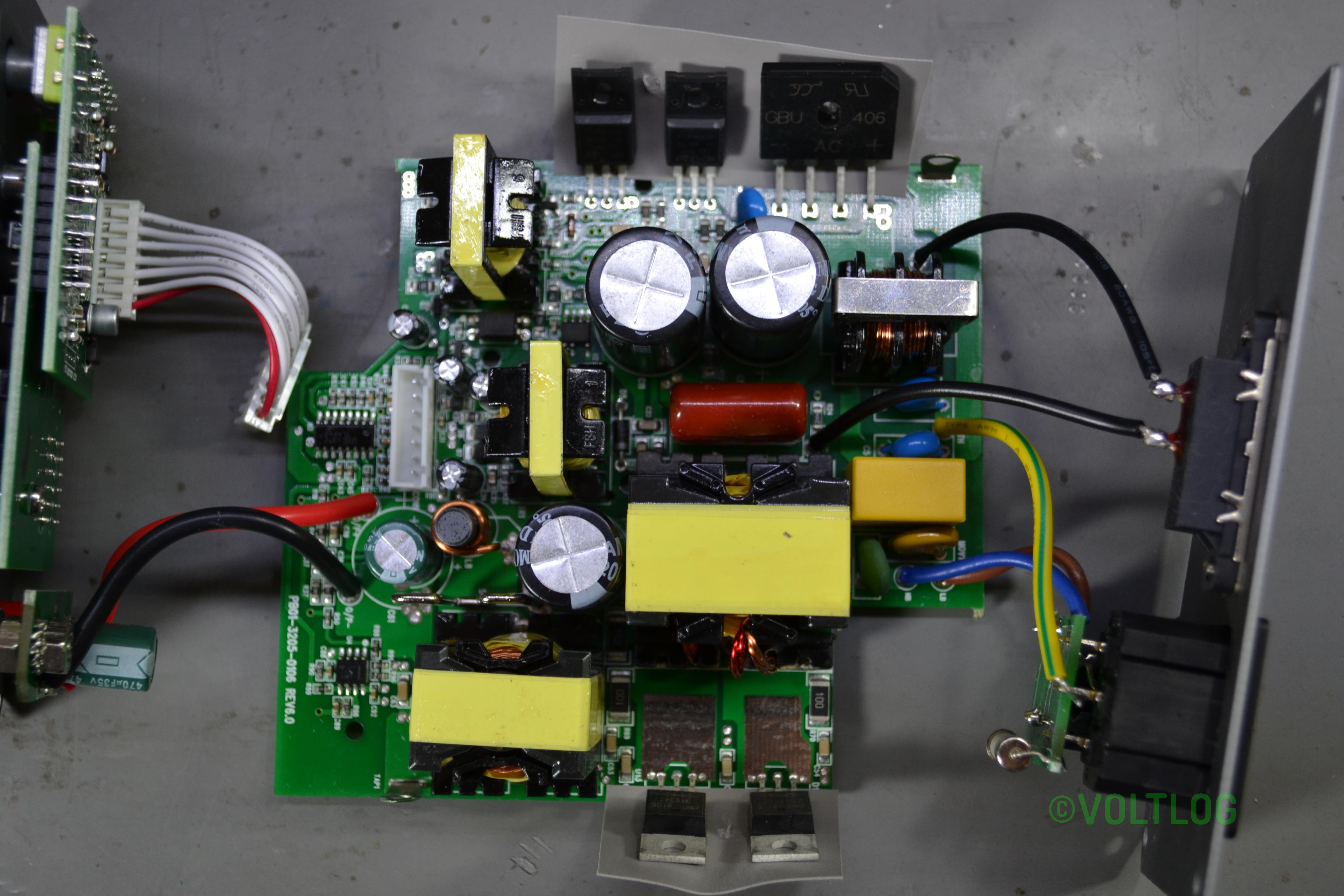
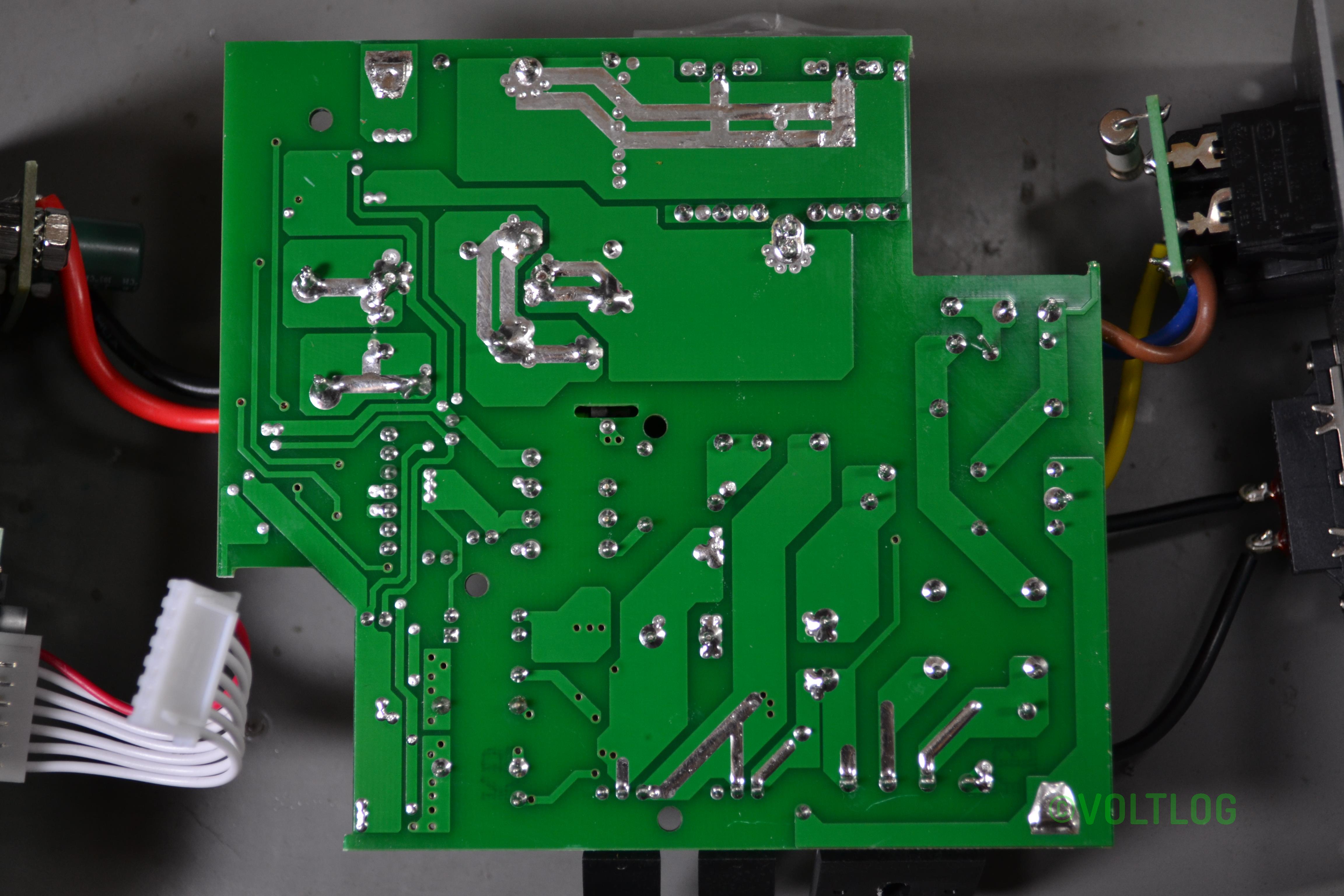
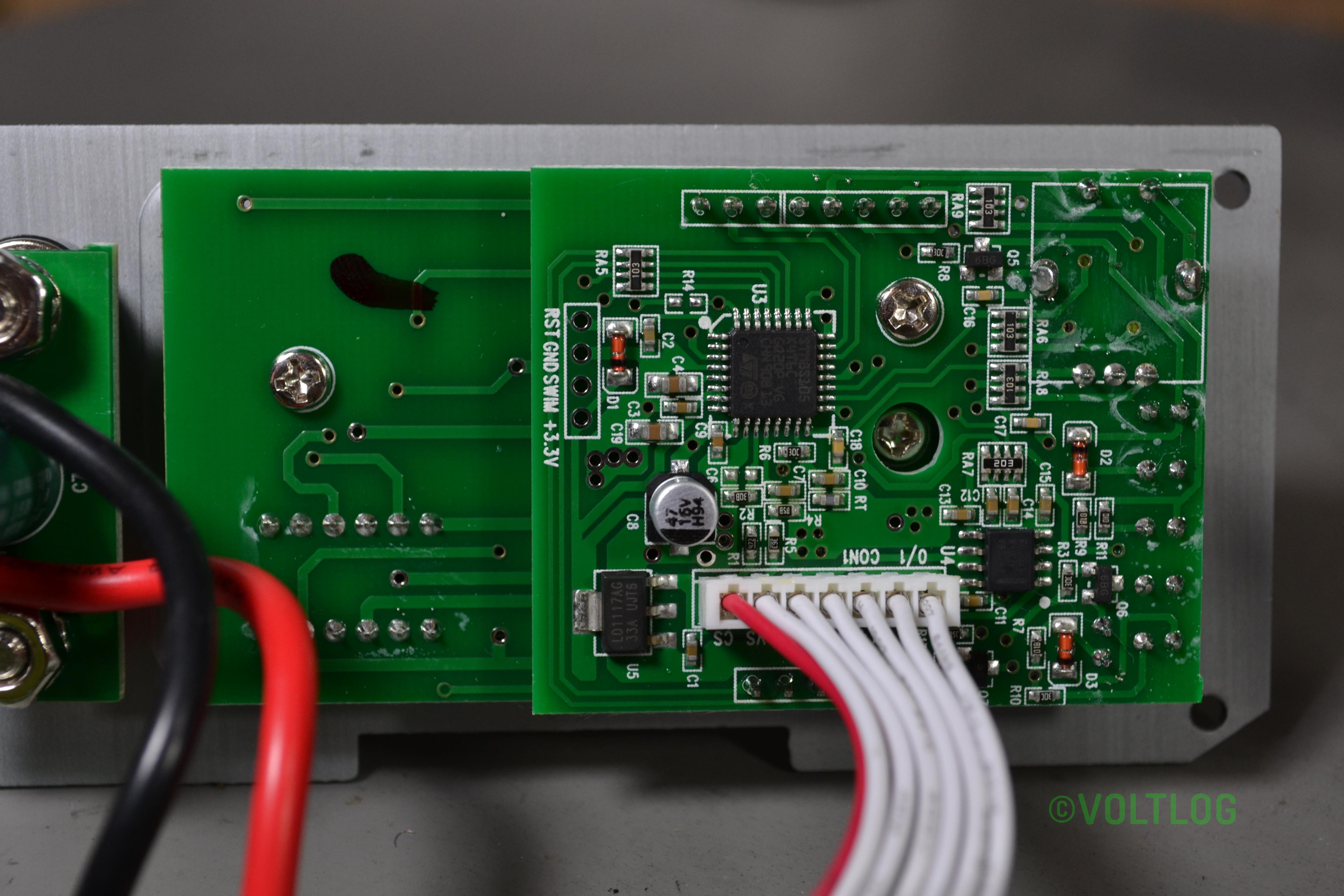
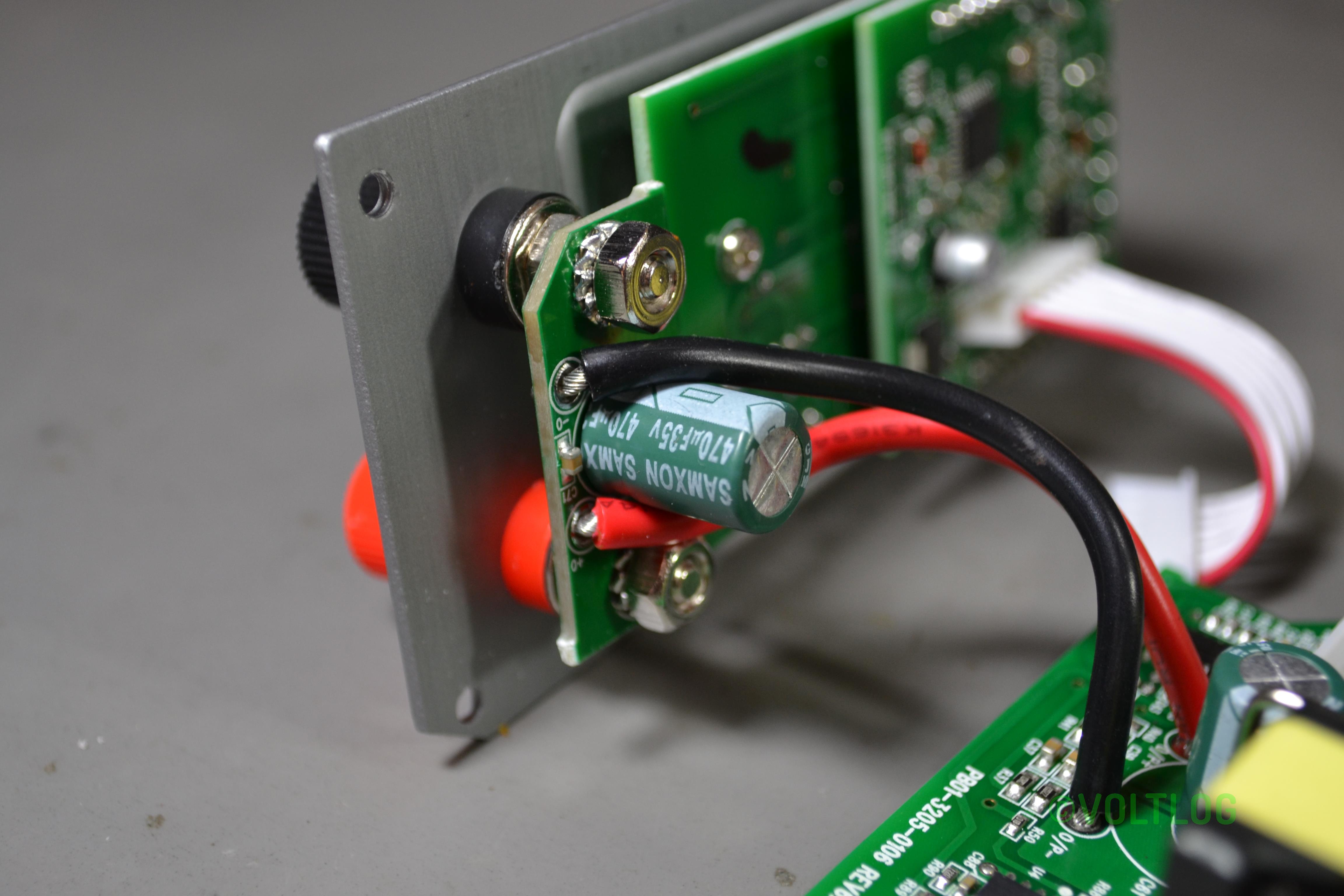
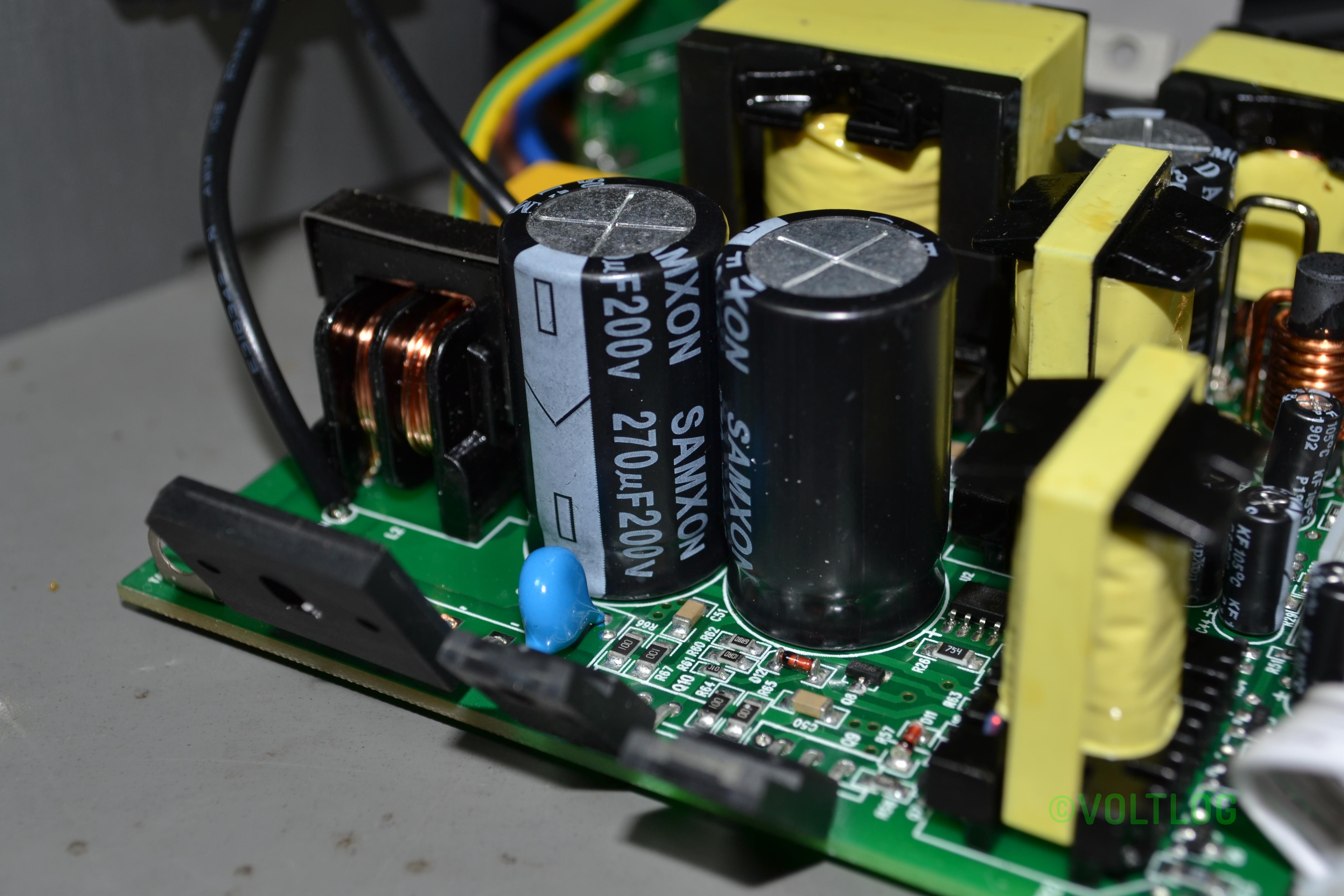
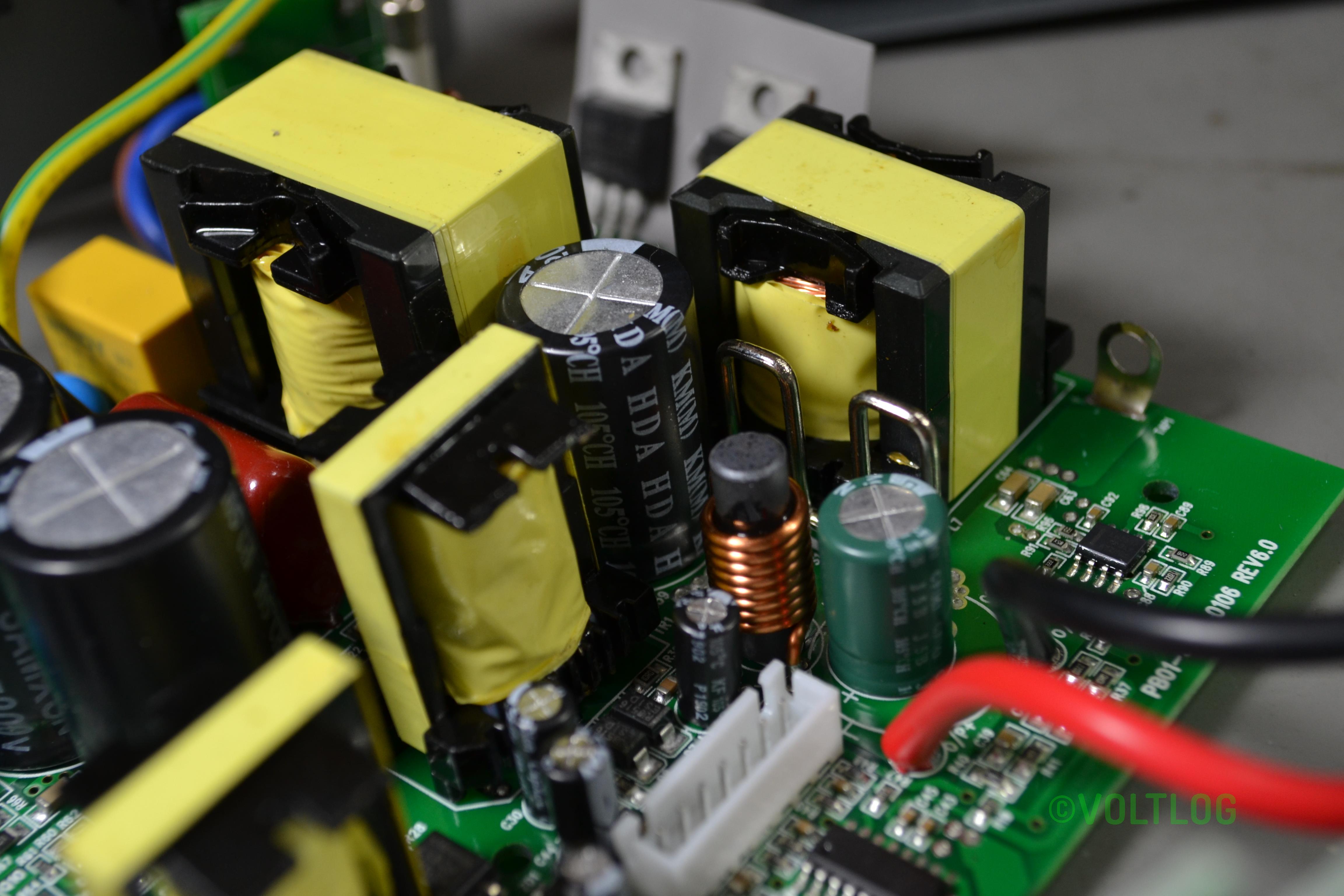
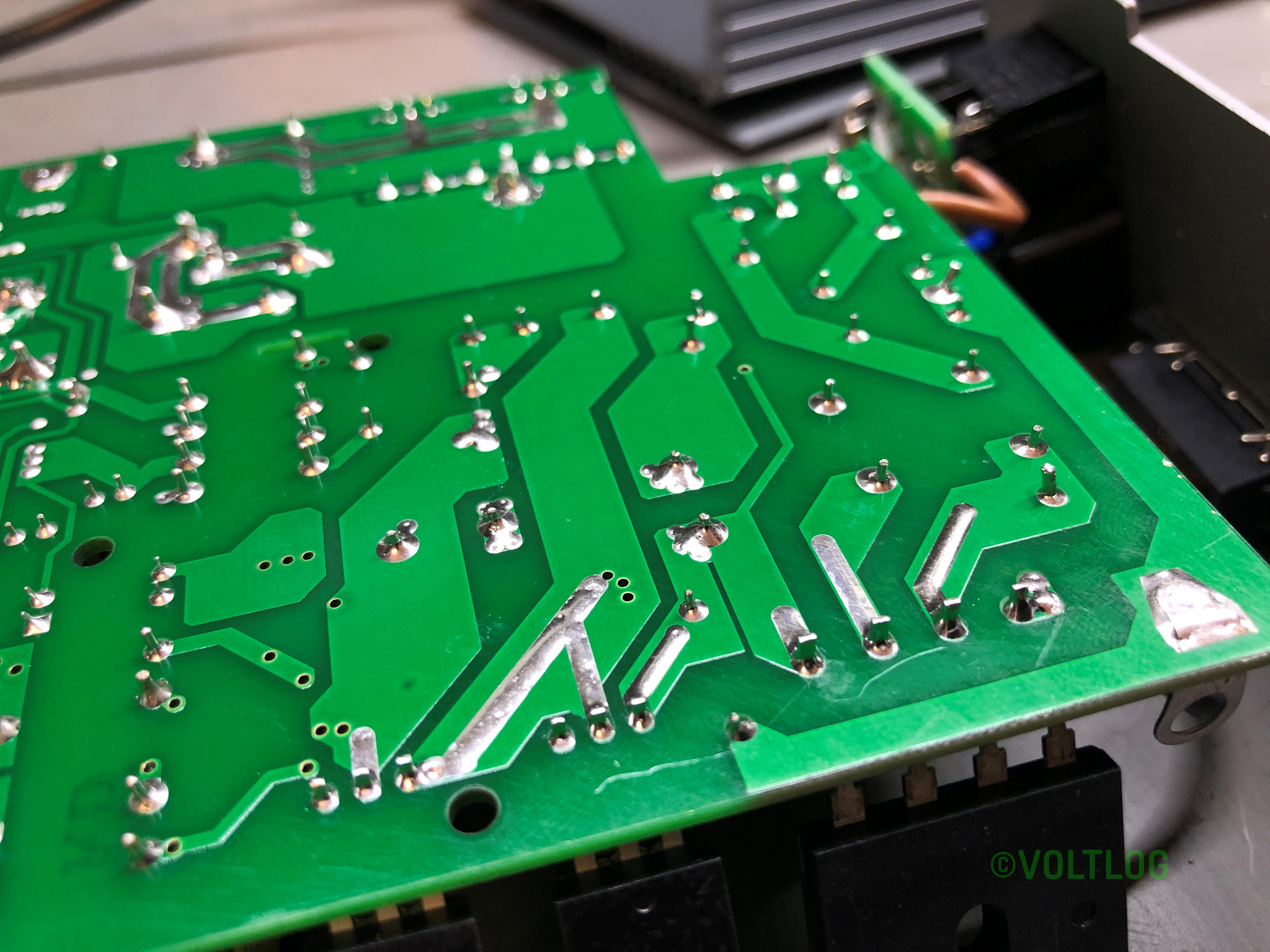
Here is a set of pictures I captured during the teardown:

Voltlog #254 – Epaper Display Pixel vs Segment Type

Welcome to a new voltlog, today we’ll have a little chat on epaper displays. You probably saw this post I made to my youtube community page a few days ago, it was about my epaper thermometer which suddenly showed the low battery sign and stopped working. I’ve only had this running for 1 month, when I received it, the battery was not connected so I thought it must have been an old battery or a bad one.

Voltlog #253 – Aneng V01A Multimeter Review & Teardown

Welcome to a new Voltlog, today it’s a multimeter review because we haven’t done one in a while and here I have the Smart Digital Multimeter which sounds like a generic name, no obvious branding on the box but granted it is featuring the multimeter on the box, it’s a color image which is not often seen on these cheap meters. On the back, the meter is shown in full black holster and we get a model number sticker, AN-V01 so this probably indicates the Aneng brand.

We’ve looked at Aneng multimeters in the past in Voltlog #114 and others and I’m gonna say this again, Aneng does not make multimeters, Aneng is just a company that rebrands existing multimeters made by other companies.

Voltlog #252 – How to fix a solder bridge

Welcome to a new Voltlog, today I want to talk about solder bridges and show you how to deal with them. A solder bridge can happen for many reasons, incorrect soldering temperature, incorrect amount of solder being used, too little or no flux, or just the incorrect technique for soldering but they all basically mean the same thing , a blob of solder shorting two or more conductive surfaces on your PCB.

Modern printed circuit boards which typically get soldermask coverage even between IC pins will help prevent this problem because molten solder normally doesn’t stick to the soldermask surface and so it’s harder to form a bridge across that surface.

But even with enough experience and the proper technique solder bridges can still happen if you do hand soldering on fine pitch ICs, it’s just part of the soldering job. It’s true that as you get better at soldering they will happen less often but don’t think they go away forever. So it’s good to know how to deal with them.

Voltlog #251 – InTheMail

Welcome to a new InTheMail, the series that will touch both your passion for electronics and your bank account at the same time. We’re going to start with this pocket multimeter, it’s the MUSTOOL MT77, let’s get it out of the box. As you can see quite a small form factor, the multimeter is very thin and has this large screen to body ratio, let’s see if they included the batteries and yes the meter turns on, it runs on two CR2032 batteries but it seems they are included. 

Voltlog #250 – Replacing Bad 4mm Banana Plugs With High Quality Hirschmann and Staubli

In this video I replace some of my old crappy 4mm banana connectors with some new Hirschmann and Staubli, high quality connectors. These should be more reliable and provide a low resistance connection between my test gear allowing me to pass high currents without any issue.

Voltlog #249 – Making Some USB Serial Converter Boards With CH340E (part 1)

Welcome to a new video, today I’m building a bunch of usb to serial converter boards because if you are into electronics and microcontrollers you will for sure need a bunch of usb to serial converters to connect your boards to a computer for example.

The idea for building these boards started when I found the CH340E converter chip on aliexpress, I like several things about this chip, it was small because it comes in MSOP10 package, it was cheap at about $0.40 a piece and it requires minimal external circuitry, in fact it only needs an external bypass cap.

Voltlog #248 – Atorch Q7 USB Meter/Load With QI Wireless Charging

So this load is built with 3 active pcb’s as well as a fourth passive one as a front panel. They are joined with these brass standoffs and I think the standoffs act as circuit paths as well because I see no wires between the different levels. In order to get the alignment right during assembly the designer of these pcbs, made these corners rounded while these ones are diagonally cut and you can see these features along an entire side. This is a neat solution overall because it saves cost and as long as the screws are tight these should provide adequate connection.

Voltlog #247 – InTheMail

Welcome to a new InTheMail, the series that will touch both your passion for electronics and your bank account at the same time. We’re going to start with this small module, at first when I ordered it I didn’t fully understood what it does but now after doing a bit of research for this mailbag it seems this is an immobiliser emulator for the VAG group. So am immobiliser is a security component of your car that will not let the ECU start the engine unless a certain key or token is present. And there might be valid reasons why you might need this emulator, for example if the immobiliser is broken, you can supposably cancel it and start the engine with this emulator or if you exchange the motor/ecu combo once again it might not be possible to use the old immobiliser and so an emulator will help.

It talks over a K-line interface which is something specific to the automotive domain but it’s basically a form of serial interface. At first I thought this was going to emulate some kind of can bus and I was planning to play with it by scanning the bus but now I realize this is useless for me.

Voltlog #246 – What if we install a heatsink on the TPS61088 boost module?

In the previous video where I took a closer look at the TPS61088, I did some measurements of the output noise but I also ran the module up to the maximum specified output power of 12V 2A. It was to be expected that the losses would turn into heat and just the small size of the board would not be enough to dissipate all that heat safely so the boost chip reached a toasty 150 degrees Celsius and inevitably went into thermal protection.

There were two questions that people mainly left in the comments of that video. First people were curious if this module would behave differently if a heatsink was installed and also some people thought about using this module in a fixed configuration, because if you remember there is a chip on this module that will switch the output voltage based on quick charge spec, depending on what the load is requesting through that protocol but people might just want a simple fixed output. To this I would add a third question of my own, what is the real efficiency figure of this module, at the maximum output.